园区网设计
{Back to Index}
Table of Contents
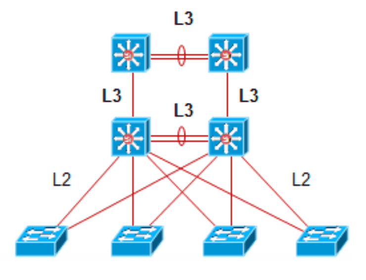
Figure 1: 基于3层交换的园区网架构
1 VTP
1.1 运行 VTP 前提
- 交换机之间起 Trunk
- 域名需要相同,默认域名为 null,只能被同步
- 认证
1.2 操作模式
1.2.1 Server(default)
- 创建,修改,删除 VLANs
- 发送或转发 advertisements
- 同步1 VLAN 配置
- 保存配置(保存在 vlan.dat)
1.2.2 Client
- 不允许 创建,修改,删除 VLANs
- 只转发 advertisements
- 同步 VLAN 配置
- 不 保存配置
1.2.3 Transparent
- 创建,修改,删除 本地 VLANs
- 只转发 advertisements
- 不 同步 VLAN 配置
- 保存配置(保存在 startup-config 中)
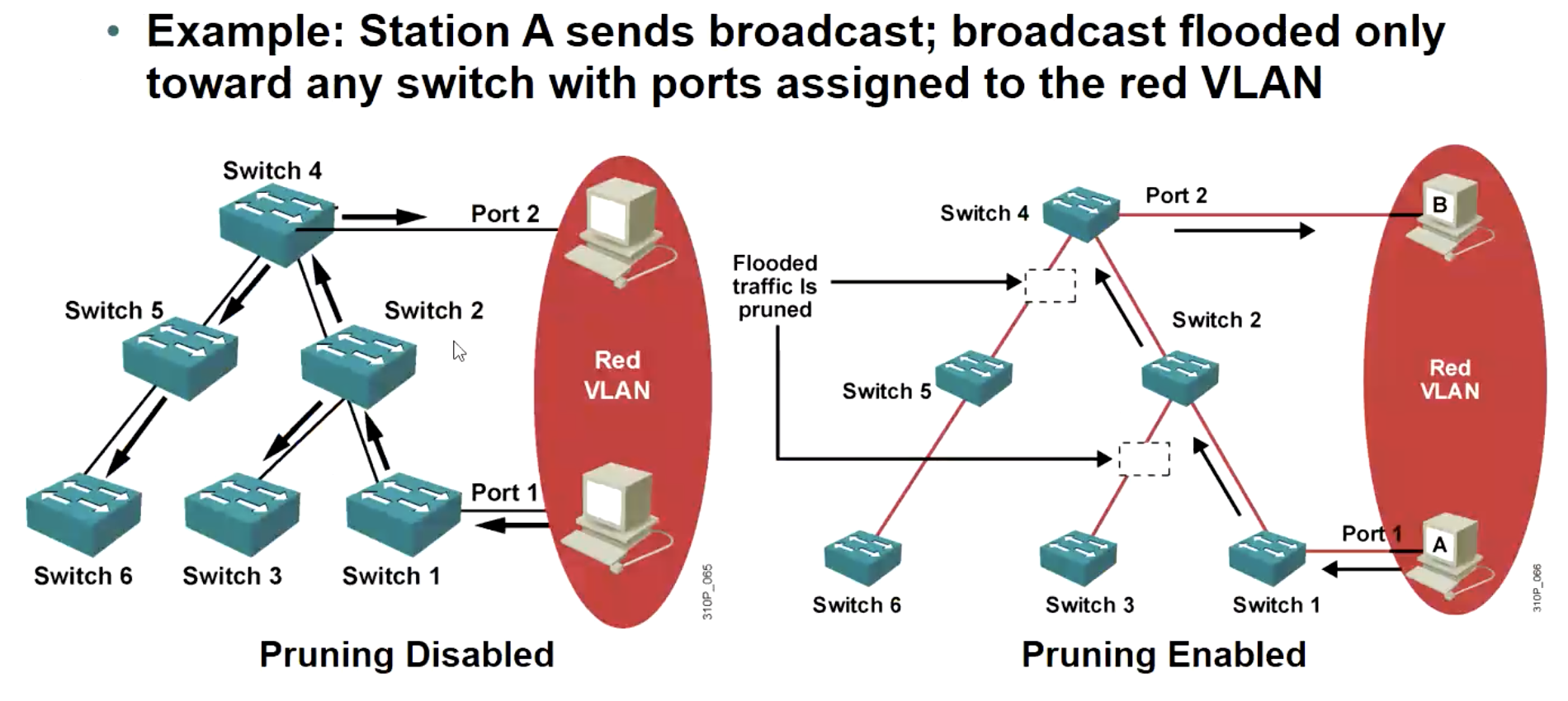
1.3 Pruning 2
用于修剪泛洪流量,即广播/组播/未知单播不会被泛洪到 有 VLAN 信息,但是没有 VLAN 接口 的交换机上。
不需要在每台交换机上都开启,在 "根" 上那个 Switch 上开启就可以,会通过 VTP 协议同步到每个交换机上的。
2 VLAN 间路由
2.1 单臂路由
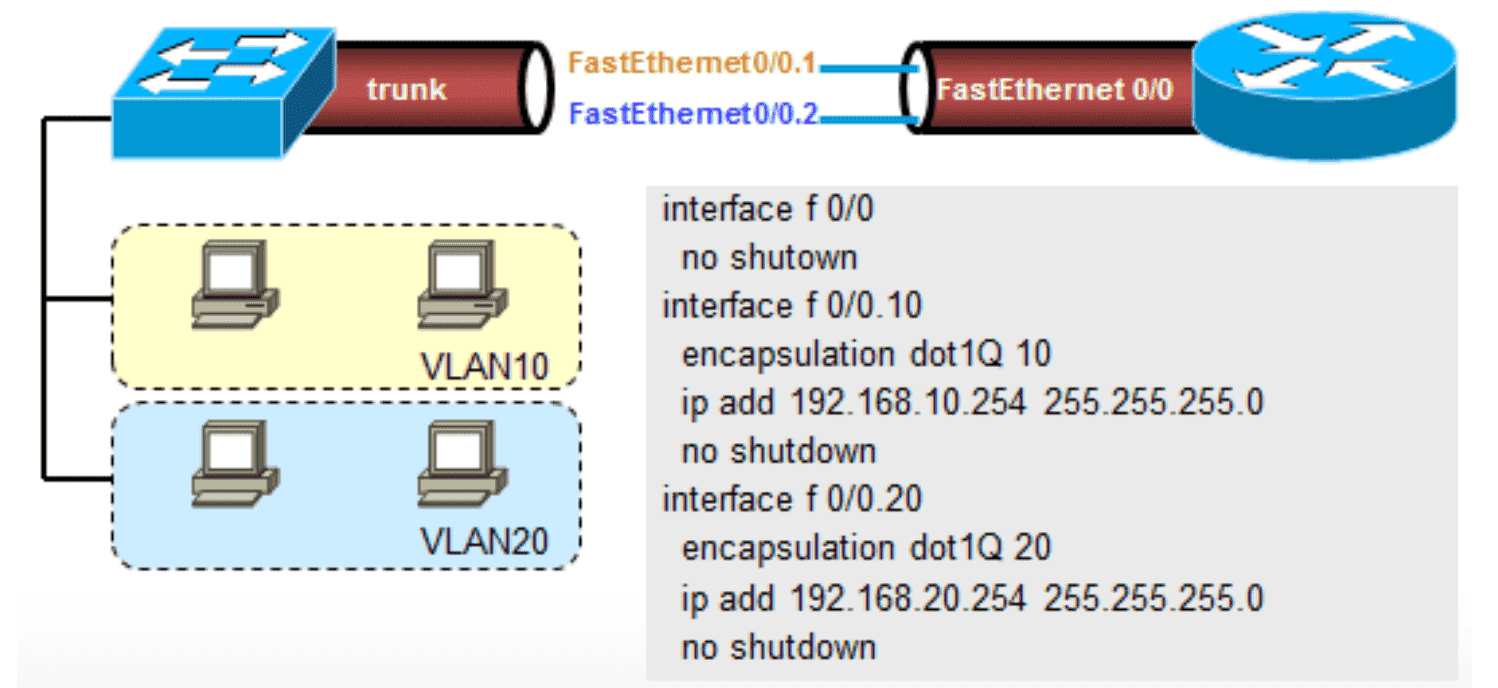
Figure 3: 单臂路由示意图
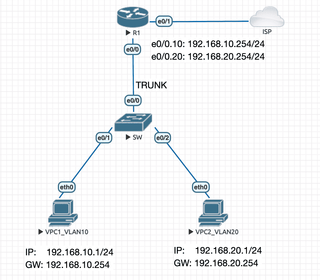
Figure 4: 实验拓扑
R1
interface Ethernet0/0.10
 encapsulation dot1Q 10
 ip address 192.168.10.254 255.255.255.0
 ip nat inside
!
interface Ethernet0/0.20
 encapsulation dot1Q 20
 ip address 192.168.20.254 255.255.255.0
 ip nat inside
!
interface Ethernet0/1
 ip address dhcp
 ip nat outside
!
ip nat inside source list NAT_ACL interface Ethernet0/1 overload
!
ip access-list standard NAT_ACL
 permit 192.168.10.0 0.0.0.255
 permit 192.168.20.0 0.0.0.255
SW
interface Ethernet0/0
 switchport trunk encapsulation dot1q
 switchport mode trunk
!
interface Ethernet0/1
 switchport access vlan 10
 switchport mode access
!
interface Ethernet0/2
 switchport access vlan 20
 switchport mode access
!
2.2 SVI
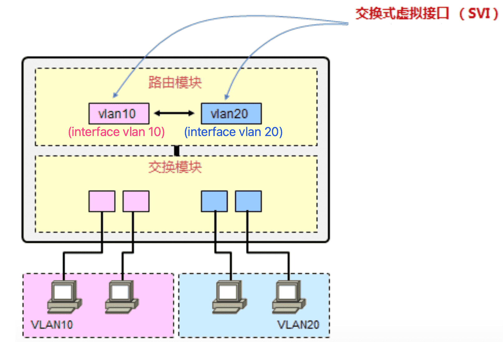
Figure 5: 虚拟接口示意图
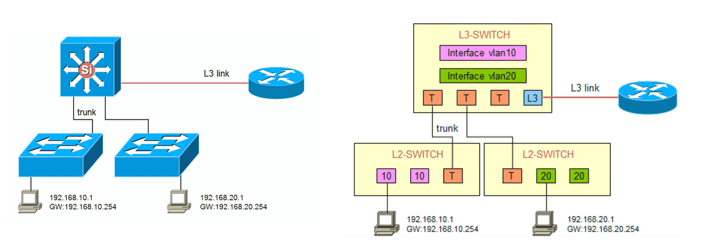
Figure 6: 经典部署案例
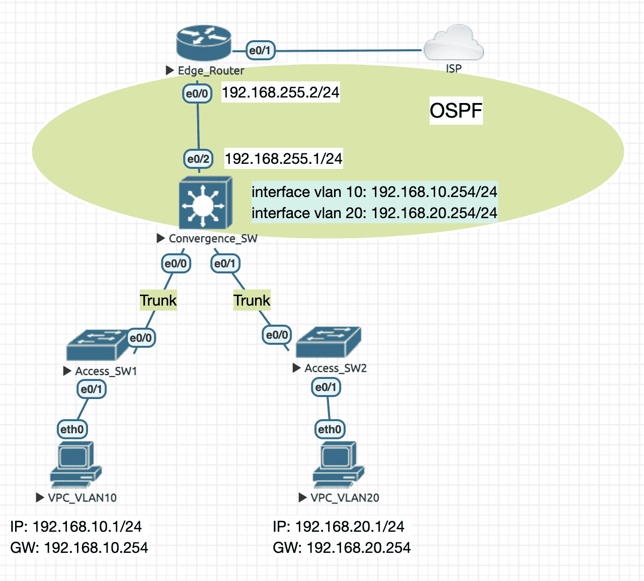
Figure 7: 实验拓扑
Edge Router
interface Ethernet0/0
 ip address 192.168.255.2 255.255.255.0
 ip nat inside
 duplex auto
!
interface Ethernet0/1
 ip address dhcp
 ip nat outside
 duplex auto
!
router ospf 1
 router-id 1.1.1.1
 network 192.168.255.2 0.0.0.0 area 0
 default-information originate
!
ip access-list standard NAT_ACL
 permit 192.168.0.0 0.0.255.255
!
ip nat inside source list NAT_ACL interface Ethernet0/1 overload
Convergence Switch
ip routing # 开启路由功能
!
interface Ethernet0/0
 switchport trunk encapsulation dot1q
 switchport mode trunk
!
interface Ethernet0/1
 switchport trunk encapsulation dot1q
 switchport mode trunk
!
interface Ethernet0/2
 no switchport
 ip address 192.168.255.1 255.255.255.0
!
interface Vlan10
 ip address 192.168.10.254 255.255.255.0
!
interface Vlan20
 ip address 192.168.20.254 255.255.255.0
!
router ospf 1
 router-id 2.2.2.2
 network 192.168.10.254 0.0.0.0 area 0
 network 192.168.20.254 0.0.0.0 area 0
 network 192.168.255.1 0.0.0.0 area 0
3 EtherChannel
这项 技术 称为 EtherChannel ,使用的 命令 是 channel-group , 逻辑接口 显示为 port-channel 。(问你爽未 🤔 )
3.1 先决条件
以太通道一旦建立完成后,就形成了一个逻辑接口,后续针对该接口的配置要在 port-channel 逻辑接口中完成。
同时,隶属于一个 port-channel 的物理接口需有相同的如下配置:
- 相同的 speed 和 duplex
- 相同的接口模式(access/trunk)
- 如果是 trunk 模式,那么 \(native vlan\) 及 \(allowed vlan\) 需相同
- 如果是 access 模式,所属 \(vlan\) 需相同
3.2 配置
- 选择用于 Channel 的端口
- 选择 PAgP 或 LACP
- 在接口组上配置 channel-group
- 设置 channel-group ID
- 根据特定的协议,选择接口模式(PAgP:on/desireable/auto/off;LACP:on/active/passive/off)
- 后续可以对生成的逻辑接口 port-channel 进行配置
3.2.1 二层通道
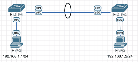
Figure 8: 二层通道拓扑
L2_SW1(config)#interface range e0/0-1
L2_SW1(config-if-range)#switchport trunk encapsulation dot1q
L2_SW1(config-if-range)#switchport mode trunk
L2_SW1(config-if-range)#channel-protocol lacp
L2_SW1(config-if-range)#channel-group 1 mode active # 对端也要用相同的 channel group ID
Creating a port-channel interface Port-channel 1
*May 22 02:05:35.174: %LINEPROTO-5-UPDOWN: Line protocol on Interface Ethernet0/0, changed state to up
*May 22 02:05:35.175: %LINEPROTO-5-UPDOWN: Line protocol on Interface Ethernet0/1, changed state to up
*May 22 02:05:39.978: %LINK-3-UPDOWN: Interface Port-channel1, changed state to up
*May 22 02:05:40.978: %LINEPROTO-5-UPDOWN: Line protocol on Interface Port-channel1, changed state to up
L2_SW1#show etherchannel 1 summary
Flags:  D - down        P - bundled in port-channel
        I - stand-alone s - suspended
        H - Hot-standby (LACP only)
        R - Layer3      S - Layer2
        U - in use      N - not in use, no aggregation
        f - failed to allocate aggregator

        M - not in use, minimum links not met
        m - not in use, port not aggregated due to minimum links not met
        u - unsuitable for bundling
        w - waiting to be aggregated
        d - default port

        A - formed by Auto LAG


Number of channel-groups in use: 1
Number of aggregators:           1

Group  Port-channel  Protocol    Ports
------+-------------+-----------+-----------------------------------------------
1      Po1(SU)         LACP      Et0/0(P)    Et0/1(P)
3.2.2 三层通道
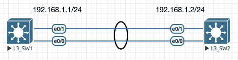
Figure 9: 三层通道拓扑
L3_SW1(config)#interface range e0/0-1
L3_SW1(config-if-range)#no switchport
L3_SW1(config-if-range)#no ip address
L3_SW1(config-if-range)#channel-group 1 mode desirable # 通过 mode 可以自动判断出使用的是 PAgP
Creating a port-channel interface Port-channel 1
L3_SW1(config-if-range)#no sh
L3_SW1(config-if-range)#int po1
L3_SW1(config-if)#ip add 192.168.1.1 255.255.255.0
L3_SW1(config-if)#no sh
*May 22 02:21:44.074: %LINEPROTO-5-UPDOWN: Line protocol on Interface Ethernet0/1, changed state to up
*May 22 02:21:44.113: %LINEPROTO-5-UPDOWN: Line protocol on Interface Ethernet0/0, changed state to up
*May 22 02:21:46.867: %LINK-3-UPDOWN: Interface Port-channel1, changed state to up
*May 22 02:21:47.871: %LINEPROTO-5-UPDOWN: Line protocol on Interface Port-channel1, changed state to up
L3_SW1#show etherchannel 1 summary
Flags:  D - down        P - bundled in port-channel
        I - stand-alone s - suspended
        H - Hot-standby (LACP only)
        R - Layer3      S - Layer2
        U - in use      N - not in use, no aggregation
        f - failed to allocate aggregator

        M - not in use, minimum links not met
        m - not in use, port not aggregated due to minimum links not met
        u - unsuitable for bundling
        w - waiting to be aggregated
        d - default port

        A - formed by Auto LAG


Number of channel-groups in use: 1
Number of aggregators:           1

Group  Port-channel  Protocol    Ports
------+-------------+-----------+-----------------------------------------------
1      Po1(RU)         PAgP      Et0/0(P)    Et0/1(P)
4 网关冗余
4.1 HSRP 3
将 同一个广播域中 (因为 HSRP 通信依赖组播) 的多台路由器上某个 接口 加入同一个 HSRP 组后, 该 HSRP 组会 虚拟 出一台路由器, 这个虚拟路由器的 IP 地址,就是内网 PC 需要配置的网关地址,而虚拟路由器的 MAC ,就是网关 IP 对应的 MAC 。
HSRP 组内的成员之间会进行选举 ,选出一个 Active 路由器,这个路由器承担实际的流量转发任务,并响应内网对于网关 IP 的 ARP 查询。
HSRP 组内的其他路由器,为 Standby 状态,实时侦听 Active 路由器的状态,以便能够在 Active 路由器故障后立即进行切换。
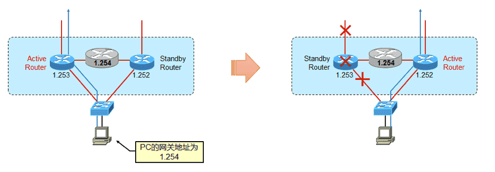
Figure 10: 逻辑示意图
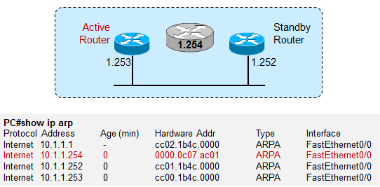
Figure 11: HSRP 使用 0000.0c07.acxx 作为虚拟路由器的 MAC , 其中 xx 是该 HSRP 组 ID
4.1.1 单组 HSRP
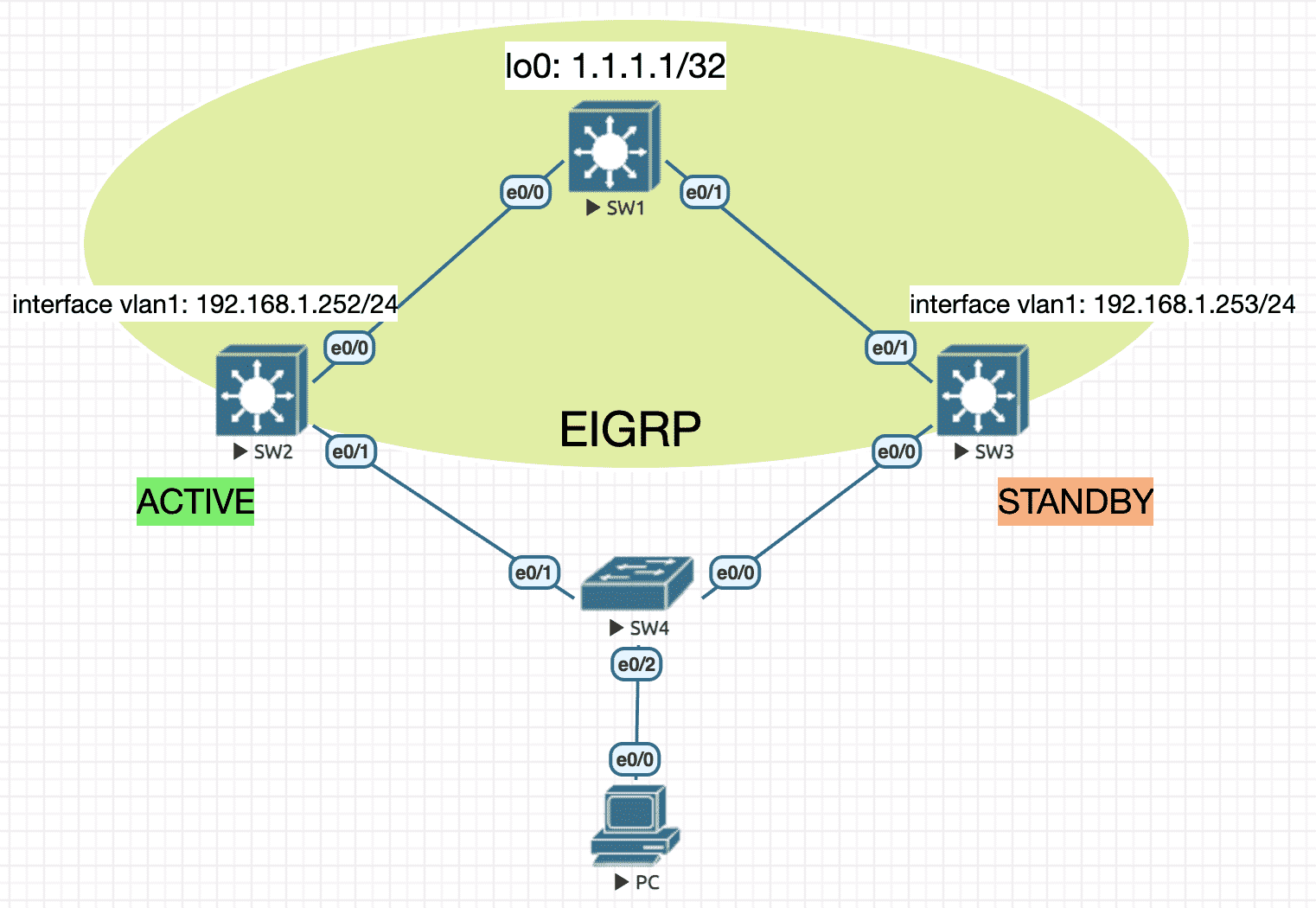
Figure 12: 实验环境
实验配置
----------------- SW1 ----------------------
en
conf t
ip routing
hostname SW1
no ip do lo
line con 0
 exec-timeout 0 0
 logging synchronous
 exit
int lo0
 ip address 1.1.1.1 255.255.255.255
int e0/0
 no switchport
 ip address 10.1.12.1 255.255.255.0
 no sh
int e0/1
 no switchport
 ip address 10.1.13.1 255.255.255.0
 no sh
router eigrp 90
 network 10.1.12.1 0.0.0.0
 network 10.1.13.1 0.0.0.0
 network 1.1.1.1 0.0.0.0

----------------- SW2 ----------------------
en
conf t
ip routing
hostname SW2
no ip do lo
line con 0
 exec-timeout 0 0
 logging synchronous
 exit
int e0/0
 no switchport
 ip address 10.1.12.2 255.255.255.0
 no sh
 exit
track 1 interface e0/0 ip routing ! define track obj for uplink
int vlan1
 ip address 192.168.1.252 255.255.255.0
 no sh
 standby 1 ip 192.168.1.254
 standby 1 priority 120 ! default priority is 100
 standby 1 preempt ! default is non-preempt
 standby 1 track 1 decrement 50 ! when uplink is down, priority will be decremented by 50
router eigrp 90
 network 10.1.12.2 0.0.0.0
 network 192.168.1.252 0.0.0.0

----------------- SW3 ----------------------
en
conf t
ip routing
hostname SW3
no ip do lo
line con 0
 exec-timeout 0 0
 logging synchronous
 exit
int e0/1
 no switchport
 ip address 10.1.13.3 255.255.255.0
 no sh
int vlan1
 ip address 192.168.1.253 255.255.255.0
 no sh
 standby 1 preempt
 standby 1 ip 192.168.1.254
router eigrp 90
 network 10.1.13.3 0.0.0.0
 network 192.168.1.253 0.0.0.0

----------------- PC ----------------------
en
conf t
no ip routing
ip default-gateway 192.168.1.254
hostname PC
no ip do lo
line con 0
 exec-timeout 0 0
 logging synchronous
 exit
int e0/0
 ip address 192.168.1.1 255.255.255.0
 no sh
查看 standby 信息
SW2#sh standby brief
                     P indicates configured to preempt.
                     |
Interface   Grp  Pri P State   Active          Standby         Virtual IP
Vl1         1    120 P Active  local           192.168.1.253   192.168.1.254
SW2#sh standby
Vlan1 - Group 1
  State is Active
    2 state changes, last state change 00:01:37
  Virtual IP address is 192.168.1.254
  Active virtual MAC address is 0000.0c07.ac01 (MAC In Use)
    Local virtual MAC address is 0000.0c07.ac01 (v1 default)
  Hello time 3 sec, hold time 10 sec
    Next hello sent in 1.760 secs
  Preemption enabled
  Active router is local
  Standby router is 192.168.1.253, priority 100 (expires in 8.336 sec)
  Priority 120 (configured 120)
    Track object 1 state Up decrement 50
  Group name is "hsrp-Vl1-1" (default)
查看转发路径
PC#traceroute 1.1.1.1
Type escape sequence to abort.
Tracing the route to 1.1.1.1
VRF info: (vrf in name/id, vrf out name/id)
  1 192.168.1.252 1 msec 1 msec 1 msec
  2 10.1.12.1 1 msec *  1 msec
将 SW2 e0/0 下电并观察 standby 信息
SW2#sh standby brief
                     P indicates configured to preempt.
                     |
Interface   Grp  Pri P State   Active          Standby         Virtual IP
Vl1         1    70  P Standby 192.168.1.253   local           192.168.1.254
再次观察转发路径
PC#traceroute 1.1.1.1
Type escape sequence to abort.
Tracing the route to 1.1.1.1
VRF info: (vrf in name/id, vrf out name/id)
  1 192.168.1.253 1 msec 0 msec 0 msec
  2 10.1.13.1 1 msec *  1 msec
4.1.2 多组 HSRP
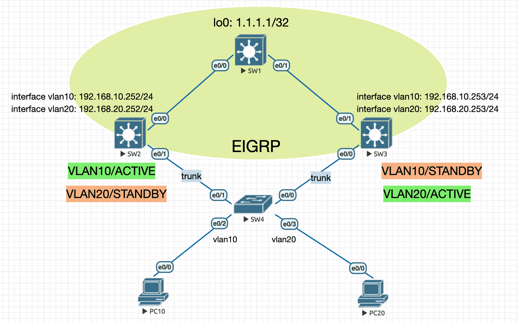
Figure 13: 实验环境
实验配置
----------------- SW1 ----------------------
en
conf t
ip routing
hostname SW1
no ip do lo
line con 0
 exec-timeout 0 0
 logging synchronous
 exit
int lo0
 ip address 1.1.1.1 255.255.255.255
int e0/0
 no switchport
 ip address 10.1.12.1 255.255.255.0
 no sh
int e0/1
 no switchport
 ip address 10.1.13.1 255.255.255.0
 no sh
router eigrp 90
 network 10.1.12.1 0.0.0.0
 network 10.1.13.1 0.0.0.0
 network 1.1.1.1 0.0.0.0

----------------- SW2 ----------------------
en
conf t
ip routing
hostname SW2
no ip do lo
line con 0
 exec-timeout 0 0
 logging synchronous
 exit
vlan 10
 name MYVLAN10
 exit
vlan 20
 name MYVLAN20
 exit
int e0/0
 no switchport
 ip address 10.1.12.2 255.255.255.0
 no sh
 exit
int e0/1
 switchport trunk encapsulation dot1q
 switchport mode trunk
 exit
int vlan10
 ip address 192.168.10.252 255.255.255.0
 no sh
 standby 10 ip 192.168.10.254
 standby 10 priority 120 ! higher priority
 standby 10 preempt !
 exit
int vlan20
 ip address 192.168.20.252 255.255.255.0
 no sh
 standby 20 ip 192.168.20.254
 standby 20 priority 100 ! lower priority
 standby 20 preempt !
 exit
router eigrp 90
 network 10.1.12.2 0.0.0.0
 network 192.168.10.252 0.0.0.0
 network 192.168.20.252 0.0.0.0

----------------- SW3 ----------------------
en
conf t
ip routing
hostname SW3
no ip do lo
line con 0
 exec-timeout 0 0
 logging synchronous
 exit
vlan 10
 name MYVLAN10
 exit
vlan 20
 name MYVLAN20
 exit
int e0/0
 switchport trunk encapsulation dot1q
 switchport mode trunk
 exit
int e0/1
 no switchport
 ip address 10.1.13.3 255.255.255.0
 no sh
int vlan10
 ip address 192.168.10.253 255.255.255.0
 no sh
 standby 10 preempt
 standby 10 priority 100 ! lower priority
 standby 10 ip 192.168.10.254 !
 exit
int vlan20
 ip address 192.168.20.253 255.255.255.0
 no sh
 standby 20 preempt
 standby 20 priority 120 ! higher priority
 standby 20 ip 192.168.20.254 !
 exit
router eigrp 90
 network 10.1.13.3 0.0.0.0
 network 192.168.10.253 0.0.0.0
 network 192.168.20.253 0.0.0.0

----------------- SW4 ----------------------
en
conf t
ip routing
hostname SW4
no ip do lo
line con 0
 exec-timeout 0 0
 logging synchronous
 exit
vlan 10
 name MYVLAN10
 exit
vlan 20
 name MYVLAN20
 exit
int range e0/0,e0/1
 switchport trunk encapsulation dot1q
 switchport mode trunk
 exit
int e0/2
 switchport mode access
 switchport access vlan 10
 exit
int e0/3
 switchport mode access
 switchport access vlan 20
 exit

----------------- PC10 ----------------------
en
conf t
no ip routing
ip default-gateway 192.168.10.254
hostname PC10
no ip do lo
line con 0
 exec-timeout 0 0
 logging synchronous
 exit
int e0/0
 ip address 192.168.10.1 255.255.255.0
 no sh

----------------- PC20 ----------------------
en
conf t
no ip routing
ip default-gateway 192.168.20.254
hostname PC20
no ip do lo
line con 0
 exec-timeout 0 0
 logging synchronous
 exit
int e0/0
 ip address 192.168.20.1 255.255.255.0
 no sh
观察 traceroute
PC10#traceroute 1.1.1.1
Type escape sequence to abort.
Tracing the route to 1.1.1.1
VRF info: (vrf in name/id, vrf out name/id)
  1 192.168.10.252 1 msec 1 msec 1 msec
  2 10.1.12.1 1 msec *  2 msec

PC20#traceroute 1.1.1.1
Type escape sequence to abort.
Tracing the route to 1.1.1.1
VRF info: (vrf in name/id, vrf out name/id)
  1 192.168.20.253 1 msec 1 msec 0 msec
  2 10.1.13.1 1 msec *  2 msec
4.1.3 MST+HSRP
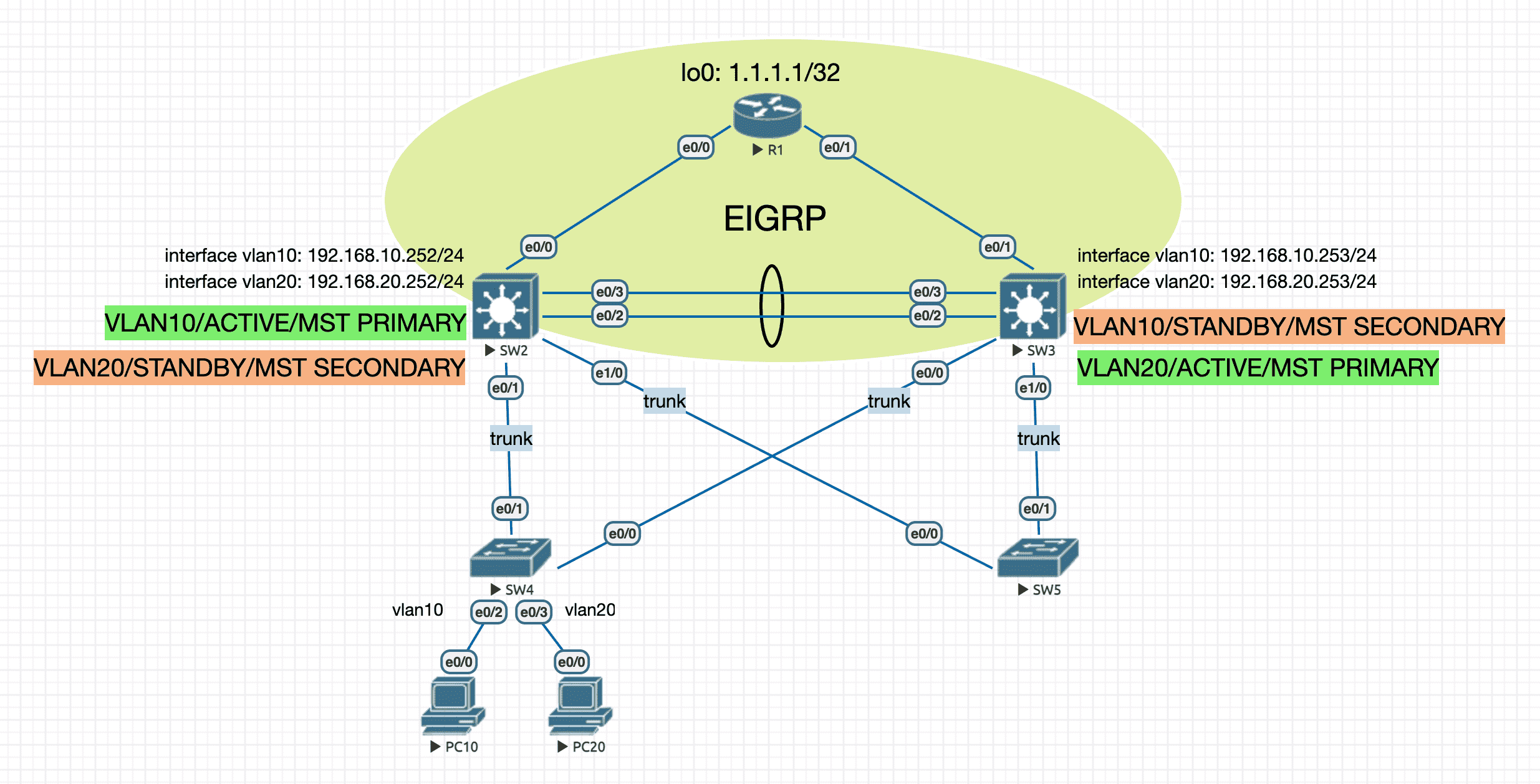
Figure 14: 双核心解决方案
使用 MST 实现 二层冗余 ,同时将不同 VLAN 的生成树主根分布在不同的汇聚层交换机上以兼顾流量负载均衡。
使用 HSRP 实现 三层网关的冗余 ,而且 ACTIVE HSRP 与相应 VLAN 的 MST 主根 落在同一台设备上。
实验配置
----------------- R1 ----------------------
en
conf t
hostname R1
no ip do lo
line con 0
 exec-timeout 0 0
 logging synchronous
 exit
int lo0
 ip address 1.1.1.1 255.255.255.255
int e0/0
 ip address 10.1.12.1 255.255.255.0
 no shutdown
int e0/1
 ip address 10.1.13.1 255.255.255.0
 no shutdown
router eigrp 90
 network 10.1.12.1 0.0.0.0
 network 10.1.13.1 0.0.0.0
 network 1.1.1.1 0.0.0.0

----------------- SW2 ----------------------
en
conf t
ip routing
hostname SW2
no ip do lo
line con 0
 exec-timeout 0 0
 logging synchronous
 exit
vlan 10
 name MYVLAN10
vlan 20
 name MYVLAN20

spanning-tree mode mst
spanning-tree mst configuration
 name cisco.com
 instance 1 vlan 10
 instance 2 vlan 20
 exit
spanning-tree mst 1 root primary
spanning-tree mst 2 root secondary

int range e0/2,e0/3
 switchport trunk encapsulation dot1q
 switchport mode trunk
 channel-group 1 mode desirable
int e0/0
 no switchport
 ip address 10.1.12.2 255.255.255.0
 no sh
int range e0/1,e1/0
 switchport trunk encapsulation dot1q
 switchport mode trunk
int vlan10
 ip address 192.168.10.252 255.255.255.0
 no sh
 standby 10 ip 192.168.10.254
 standby 10 priority 120 ! higher priority
 standby 10 preempt !
int vlan20
 ip address 192.168.20.252 255.255.255.0
 no sh
 standby 20 ip 192.168.20.254
 standby 20 priority 100 ! lower priority
 standby 20 preempt !
router eigrp 90
 network 10.1.12.2 0.0.0.0
 network 192.168.10.252 0.0.0.0
 network 192.168.20.252 0.0.0.0

----------------- SW3 ----------------------
en
conf t
ip routing
hostname SW3
no ip do lo
line con 0
 exec-timeout 0 0
 logging synchronous
 exit
vlan 10
 name MYVLAN10
vlan 20
 name MYVLAN20

spanning-tree mode mst
spanning-tree mst configuration
 name cisco.com
 instance 1 vlan 10
 instance 2 vlan 20
 exit
spanning-tree mst 1 root secondary
spanning-tree mst 2 root primary

int range e0/2,e0/3
 switchport trunk encapsulation dot1q
 switchport mode trunk
 channel-group 1 mode desirable
int range e0/0,e1/0
 switchport trunk encapsulation dot1q
 switchport mode trunk
int e0/1
 no switchport
 ip address 10.1.13.3 255.255.255.0
 no sh
int vlan10
 ip address 192.168.10.253 255.255.255.0
 no sh
 standby 10 preempt
 standby 10 priority 100 ! lower priority
 standby 10 ip 192.168.10.254 !
int vlan20
 ip address 192.168.20.253 255.255.255.0
 no sh
 standby 20 preempt
 standby 20 priority 120 ! higher priority
 standby 20 ip 192.168.20.254 !
router eigrp 90
 network 10.1.13.3 0.0.0.0
 network 192.168.10.253 0.0.0.0
 network 192.168.20.253 0.0.0.0

----------------- SW4 ----------------------
en
conf t
ip routing
hostname SW4
no ip do lo
line con 0
 exec-timeout 0 0
 logging synchronous
 exit
vlan 10
 name MYVLAN10
 exit
vlan 20
 name MYVLAN20
 exit
int range e0/0,e0/1
 switchport trunk encapsulation dot1q
 switchport mode trunk
 exit
int e0/2
 switchport mode access
 switchport access vlan 10
 exit
int e0/3
 switchport mode access
 switchport access vlan 20
 exit

----------------- SW5 ----------------------
en
conf t
ip routing
hostname SW5
no ip do lo
line con 0
 exec-timeout 0 0
 logging synchronous
 exit
vlan 10
 name MYVLAN10
 exit
vlan 20
 name MYVLAN20
 exit
int range e0/0,e0/1
 switchport trunk encapsulation dot1q
 switchport mode trunk
 exit

----------------- PC10 ----------------------
en
conf t
no ip routing
ip default-gateway 192.168.10.254
hostname PC10
no ip do lo
line con 0
 exec-timeout 0 0
 logging synchronous
 exit
int e0/0
 ip address 192.168.10.1 255.255.255.0
 no sh

----------------- PC20 ----------------------
en
conf t
no ip routing
ip default-gateway 192.168.20.254
hostname PC20
no ip do lo
line con 0
 exec-timeout 0 0
 logging synchronous
 exit
int e0/0
 ip address 192.168.20.1 255.255.255.0
 no sh
4.2 VRRP
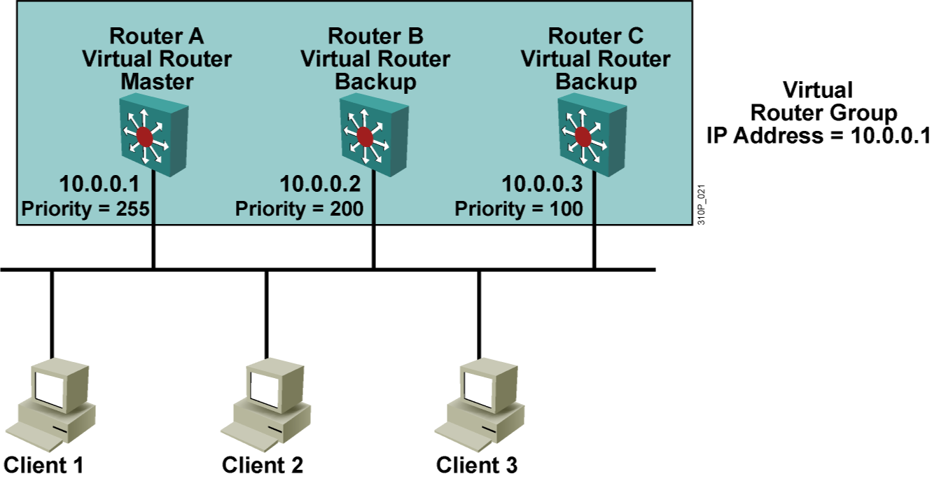
Figure 15: Virtual Route Redundancy Protocol
4.2.1 与 HSRP 的区别
- 使用 Master/Slave 表示主备关系
- VIP 可以是虚拟出来的, 也可以是真实存在的地址(此时 priority=255) ,而 HSRP 只能使用虚拟出来的 IP 4
- 只有 Master 每 1 秒发一次 Hello
- 默认启用抢占
- 不抑制 ICMP redirect 功能,而 HSRP 不使用 redirect
4.2.2 实验
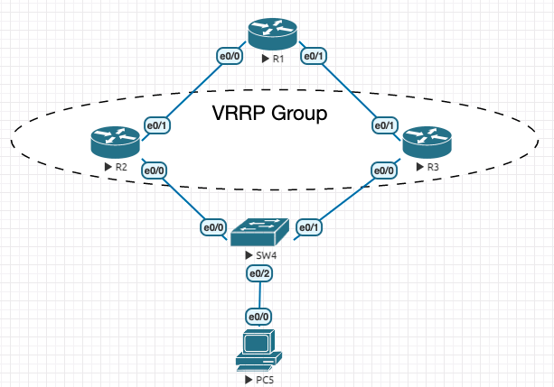
Figure 16: 实验环境
配置清单
----------------- R1 ----------------------
en
conf t
 hostname R1
 no ip do lo
 line con 0
  exec-timeout 0 0
  logging synchronous
 exit
 int e0/0
  ip address 10.1.12.1 255.255.255.0
  no sh
 !
 ip route 192.168.0.0 255.255.0.0 10.1.12.2
 ip route 192.168.0.0 255.255.0.0 10.1.13.3
 int e0/1
  ip address 10.1.13.1 255.255.255.0
  no sh
 !
end

----------------- R2 ----------------------
en
conf t
 hostname R2
 no ip do lo
 line con 0
  exec-timeout 0 0
  logging synchronous
 exit
 int e0/0
  ip address 192.168.23.2 255.255.255.0
  no sh
 !
 int e0/1
  ip address 10.1.12.2 255.255.255.0
  no sh
 !
 ip route 0.0.0.0 0.0.0.0 10.1.12.1
 int e0/0
  vrrp 10 ip 192.168.23.2 ! real ip is also allowed
  ! no need to set priority here. Priority change will have no effect whilst interface is VRRP address owner
 !
end

----------------- R3 ----------------------
en
conf t
 hostname R3
 no ip do lo
 line con 0
  exec-timeout 0 0
  logging synchronous
 exit
 int e0/0
  ip address 192.168.23.3 255.255.255.0
  no sh
 !
 int e0/1
  ip address 10.1.13.3 255.255.255.0
  no sh
 !
 ip route 0.0.0.0 0.0.0.0 10.1.13.1
 int e0/0
  vrrp 10 ip 192.168.23.2
  vrrp 10 priority 100
 !
end

----------------- PC5 ----------------------
en
conf t
 hostname PC5
 no ip do lo
 line con 0
  exec-timeout 0 0
  logging synchronous
 exit
 no ip routing
 ip default-gateway 192.168.23.2
 int e0/0
  ip address 192.168.23.5 255.255.255.0
  no sh
 !
end
查看状态:
R3#sh vrrp
Ethernet0/0 - Group 10
  State is Backup
  Virtual IP address is 192.168.23.2
  Virtual MAC address is 0000.5e00.010a
  Advertisement interval is 1.000 sec
  Preemption enabled
  Priority is 100
  Master Router is 192.168.23.2, priority is 255
  Master Advertisement interval is 1.000 sec
  Master Down interval is 3.609 sec (expires in 2.812 sec)

R3#sh vrrp brief
Interface          Grp Pri Time  Own Pre State   Master addr     Group addr
Et0/0              10  100 3609       Y  Backup  192.168.23.2    192.168.23.2
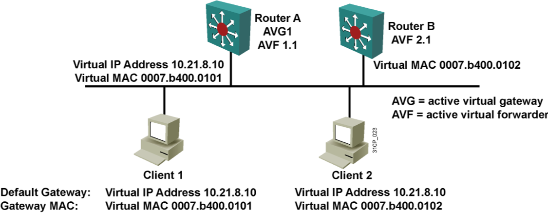
4.3 GLBP
网关 负载均衡 ,设计思想是 单虚拟 IP 多虚拟 MAC 。
5 流量镜像
5.1 SPAN
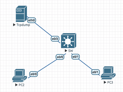
Figure 18: 实验环境(将e0/0镜像到e0/2)
实验配置
----------------- SW ----------------------
en
conf t
hostname SW
no ip do lo
line con 0
  exec-timeout 0 0
  logging synchronous
  exit
int range e0/0,e0/1
  spanning-tree portfast ! nice to have
  exit
monitor session 1 source interface e0/0
monitor session 1 destination interface e0/2

----------------- PC2 ----------------------
en
conf t
hostname PC2
no ip do lo
line con 0
  exec-timeout 0 0
  logging synchronous
  exit
int e0/0
  ip address 100.1.1.2 255.255.255.0
  no sh

----------------- PC3 ----------------------
en
conf t
hostname PC3
no ip do lo
line con 0
  exec-timeout 0 0
  logging synchronous
  exit
int e0/1
  ip address 100.1.1.3 255.255.255.0
  no sh
查看 monitor session 信息
SW#sh monitor session 1
Session 1
---------
Type                     : Local Session
Source Ports             :
    Both                 : Et0/0
Destination Ports      : Et0/2
    Encapsulation      : Native


SW#sh monitor session 1 detail
Session 1
---------
Type                     : Local Session
Description            : -
Source Ports             :
    RX Only              : None
    TX Only              : None
    Both                 : Et0/0
Source VLANs             :
    RX Only              : None
    TX Only              : None
    Both                 : None
Source RSPAN VLAN      : None
Destination Ports      : Et0/2
    Encapsulation      : Native
Filter VLANs           : None
Dest RSPAN VLAN        : None
5.2 RSPAN
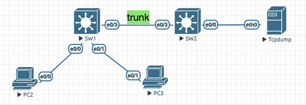
Figure 19: 实验环境
实验配置
----------------- SW1 ----------------------
en
conf t
hostname SW1
no ip do lo
line con 0
  exec-timeout 0 0
  logging synchronous
  exit
vlan 100
  name REMOTE_VLAN_100 ! dedicated for rspan
  remote-span
  exit
int range e0/0,e0/1
  spanning-tree portfast ! nice to have
  exit
int e0/3
 switchport trunk encapsulation dot1q
 switchport mode trunk
 exit
monitor session 1 source interface e0/0
monitor session 1 destination remote vlan 100

----------------- SW2 ----------------------
en
conf t
hostname SW2
no ip do lo
line con 0
  exec-timeout 0 0
  logging synchronous
  exit
vlan 100
  name REMOTE_VLAN_100
  remote-span
  exit
int e0/0
  spanning-tree portfast ! nice to have
  exit
int e0/3
 switchport trunk encapsulation dot1q
 switchport mode trunk
monitor session 1 source remote vlan 100
monitor session 1 destination interface e0/0

----------------- PC2 ----------------------
en
conf t
hostname PC2
no ip do lo
line con 0
  exec-timeout 0 0
  logging synchronous
  exit
int e0/0
  ip address 100.1.1.2 255.255.255.0
  no sh

----------------- PC3 ----------------------
en
conf t
hostname PC3
no ip do lo
line con 0
  exec-timeout 0 0
  logging synchronous
  exit
int e0/1
  ip address 100.1.1.3 255.255.255.0
  no sh
查看 monitor session 信息
SW2#sh monitor session 1
Session 1
---------
Type                     : Remote Destination Session
Source RSPAN VLAN      : 100
Destination Ports      : Et0/0
    Encapsulation      : Native


SW2#sh monitor session 1 detail
Session 1
---------
Type                     : Remote Destination Session
Description            : -
Source Ports             :
    RX Only              : None
    TX Only              : None
    Both                 : None
Source VLANs             :
    RX Only              : None
    TX Only              : None
    Both                 : None
Source RSPAN VLAN      : 100
Destination Ports      : Et0/0
    Encapsulation      : Native
Filter VLANs           : None
Dest RSPAN VLAN        : None
6 网络服务
6.1 NTP 5
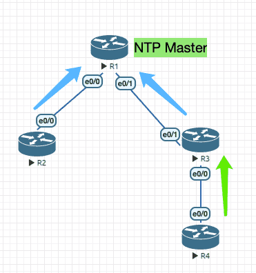
Figure 20: 实验环境
实验配置
----------------- R1 ----------------------
en
clock set 00:00:00 11 Jul 2021 ! set time
debug ntp events
conf t
hostname R1
no ip do lo
line con 0
 exec-timeout 0 0
 logging synchronous
 exit
int e0/0
 ip address 10.1.12.1 255.255.255.0
 no sh
 exit
int e0/1
 ip address 10.1.13.1 255.255.255.0
 no sh
 exit
ntp master ! default stratum is 8

----------------- R2 ----------------------
en
debug ntp events
conf t
hostname R2
no ip do lo
line con 0
 exec-timeout 0 0
 logging synchronous
 exit
int e0/0
 ip address 10.1.12.2 255.255.255.0
 no sh
 exit
ntp server 10.1.12.1 ! sync with master

----------------- R3 ----------------------
en
debug ntp events
conf t
hostname R3
no ip do lo
line con 0
 exec-timeout 0 0
 logging synchronous
 exit
int e0/0
 ip address 10.1.34.3 255.255.255.0
 no sh
int e0/1
 ip address 10.1.13.3 255.255.255.0
 no sh
 exit
ntp server 10.1.13.1 ! sync with master

----------------- R4 ----------------------
en
debug ntp events
conf t
hostname R4
no ip do lo
line con 0
 exec-timeout 0 0
 logging synchronous
 exit
int e0/0
 ip address 10.1.34.4 255.255.255.0
 no sh
ntp peer 10.1.34.3 ! sync with peer
6.2 DHCP
6.2.1 报文交互
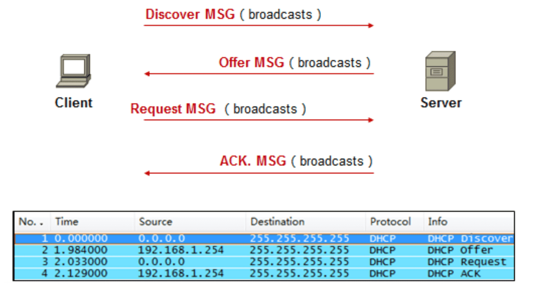
Figure 21: DHCP 报文交互过程
6.2.1.1 中继交互
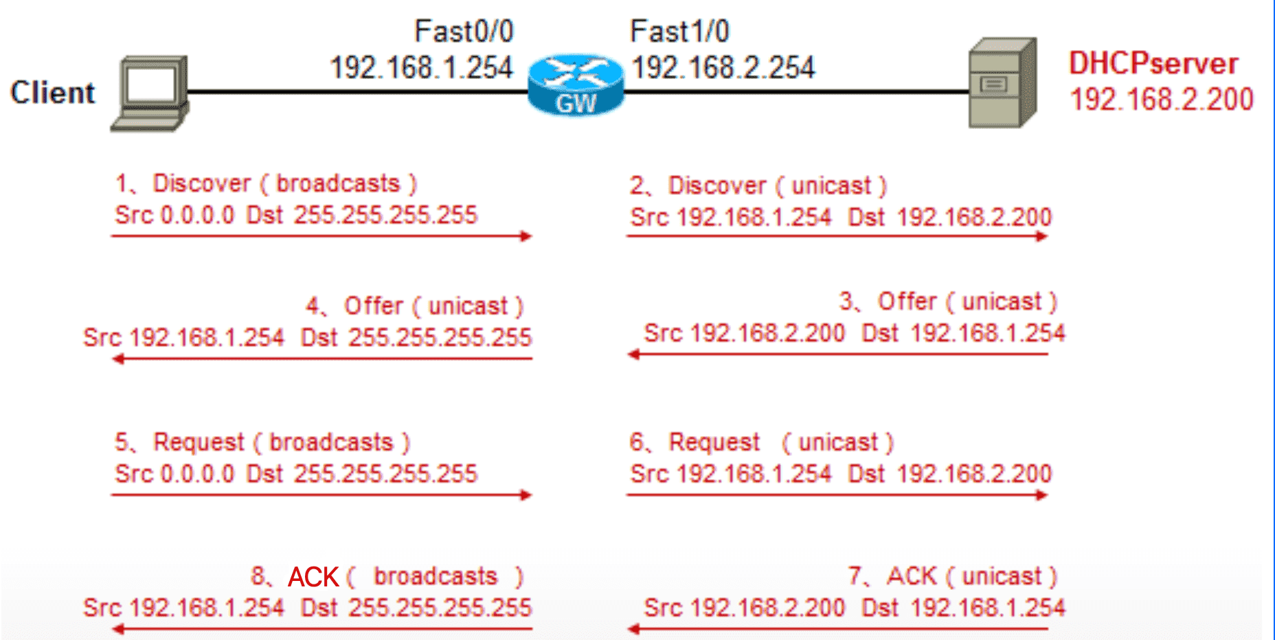
Figure 22: 中继交互过程
6.2.2 基本配置
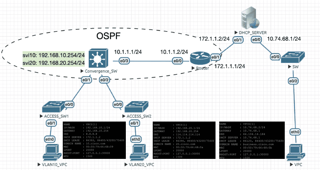
Figure 23: 实验环境
Convergence SW
interface Vlan10
 ip address 192.168.10.254 255.255.255.0
 ip helper-address 172.1.1.2
!
interface Vlan20
 ip address 192.168.20.254 255.255.255.0
 ip helper-address 172.1.1.2
!
DHCP Server
no ip routing ip default-gateway 172.1.1.1! ip dhcp excluded-address 192.168.10.254 # 排除某些 IP ip dhcp excluded-address 192.168.20.254 ip dhcp excluded-address 10.74.68.1 ! ip dhcp pool DHCP_POOL_10 network 192.168.10.0 255.255.255.0 default-router 192.168.10.254 # 网关 domain-name 10.cisco.com dns-server 8.8.8.8 ! ip dhcp pool DHCP_POOL_20 network 192.168.20.0 255.255.255.0 default-router 192.168.20.254 dns-server 114.114.114.114 domain-name 20.cisco.com ! # 如果不定义 POOL_68 ,则当 VPC 请求地址时,DHCP 服务会报错:DHCPD: there is no address pool for 10.74.68.1 # 说明地址池的选择由入口地址或是中继地址决定 ip dhcp pool DHCP_POOL_68 network 10.74.68.0 255.255.255.0 domain-name business.cisco.com dns-server 64.104.14.184 default-router 10.74.68.1
DHCP_Server#sh ip dhcp binding
Bindings from all pools not associated with VRF:
IP address          Client-ID/              Lease expiration        Type
                    Hardware address/
                    User name
10.74.68.2          0100.5079.6668.0b       May 22 2021 04:28 PM    Automatic
192.168.10.1        0100.5079.6668.09       May 22 2021 04:14 PM    Automatic
192.168.20.1        0100.5079.6668.0a       May 22 2021 04:17 PM    Automatic
6.3 DNS
ip dns server
ip domain-lookup
ip name-server 64.104.76.247

! define A record
ip host test.mysite.com 192.168.0.5
ip host mail.mysite.com 192.168.0.5
! define MX record
ip host mysite.com mx 10 mail.mysite.com
ip host mysite.com mx 20 mail.isp.com
6.4 CA
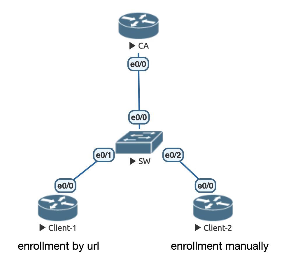
初始配置
! ------------------ CA ------------------------
en
conf t
ip domain-name cisco.com
alias exec ai sh ip int | in is.*up|Internet address|Secondary address
alias exec ii sh ip int b | ex un
alias exec i sh ip int b
alias exec rr sh ip route | begin Gateway
hostname CA
no ip do lo
line con 0
 exec-timeout 0 0
 logging synchronous
int e0/0
 ip add 192.168.1.10 255.255.255.0
 no sh
!
! ------------------ Client-1 ------------------------
en
conf t
ip domain-name cisco.com
alias exec ai sh ip int | in is.*up|Internet address|Secondary address
alias exec ii sh ip int b | ex un
alias exec i sh ip int b
alias exec rr sh ip route | begin Gateway
hostname Client-1
no ip do lo
line con 0
 exec-timeout 0 0
 logging synchronous
int e0/0
 ip add 192.168.1.1 255.255.255.0
 no sh
!
! ------------------ Client-2 ------------------------
en
conf t
ip domain-name cisco.com
alias exec ai sh ip int | in is.*up|Internet address|Secondary address
alias exec ii sh ip int b | ex un
alias exec i sh ip int b
alias exec rr sh ip route | begin Gateway
hostname Client-2
no ip do lo
line con 0
 exec-timeout 0 0
 logging synchronous
int e0/0
 ip add 192.168.1.2 255.255.255.0
 no sh
!
trustpoint 可以理解为 证书配置容器 ,并对应一个证书链, 不是只针对 CA 。
配置 CA
! ---------- CA ------------
ip http server

crypto key generate rsa label CA modulus 2048 exportable ! create keypair
! sh cry key mypubkey rsa ! show keypair
! cry key export rsa CA pem terminal 3des Cisco123 ! export key with passwd, and you can check it with: openssl rsa -in priv.key

crypto pki server CA ! create certificate authority server, 'CA' is also the name for keypair
 issuer-name CN=ca.cisco.com,C=CN,L=Shanghai
 lifetime certificate 365 ! lifetime for client cert
 lifetime ca-certificate 3650 ! lifetime for CA
 lifetime crl 24 ! recommended poll interval hours for crl query
 database level minimum
 grant auto
 no shutdown ! enable CA server
 ! you need to input password here, this passwd is mainly used for auto-generated keypair.
 ! since we create keypair manually, this passwd is unneccesary in fact
!
sh cry pki server ! show pki server status
sh cry pki certificates ! show all certs
使用 url 方式申请个人证书(SCEP)
! ------------ Client-1 -----------------
cry pki trustpoint TP_Client_1
 enrollment url http://192.168.1.10 ! CA url
!
cry pki authenticate TP_Client_1 ! request and install CA cert

cry key generate rsa label KEY1 modulus 2048 ! generate keypair myself
cry pki trustpoint TP_Client_1
 rsakeypair KEY1 ! specify keypair mannualy
 subject-name CN=client-1.cisco.com,OU=CRDC
!
ip domain name cisco.com
crypto pki enroll TP_Client_1 ! request cert
! need to input password
使用复制黏贴方式申请
! ------------ Client-2 ---------------
cry pki trustpoint TP_Client_2
 enrollment terminal
!
cry pki authenticate TP_Client_2
! paste CA cert here manually, on CA(conf): cry pki export CA pem terminal

ip domain name cisco.com
cry pki trustpoint TP_Client_2
 subject-name CN=client-2.cisco.com,OU=CRDC
 ! will create new keypair when requesting cert
!
crypto pki enroll TP_Client_2 ! request cert
! copy csr and paste it on CA(#): cry pki server CA request pkcs10 terminal
cry pki import TP_Client_2 certificate ! paste cert
sh cry pki cert ! check
7 Security
7.1 Anti MAC attack
7.1.1 Port Security
基于源 MAC 地址 放行 流量。
- 限制条件
- 指定可访问的 MAC 地址
- 最多可以学习到的 MAC 地址数量
- 限制措施
shutdown
将端口置位
err-disable并发送 SNMP Traprestrict
丢弃数据帧并发送 SNMP Trap
protect
丢弃数据帧但不发送 SNMP Trap
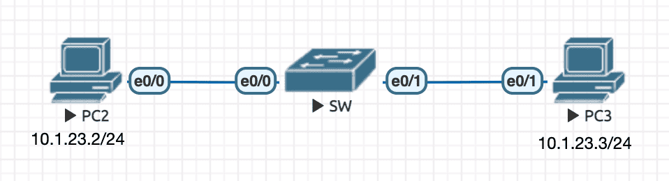
Figure 25: 实验环境
实验配置
----------------- SW ----------------------
en
conf t
hostname SW
no ip do lo
line con 0
 exec-timeout 0 0
 logging synchronous
 exit
int e0/0
 switchport mode access
 shutdown ! better to shutdown first
 switchport port-security ! must have this config to enable port-security feature
 switchport port-security mac-address aaaa.bbbb.cccc
 no shutdown

----------------- PC2 ----------------------
en
conf t
hostname PC2
no ip routing
no ip do lo
line con 0
 exec-timeout 0 0
 logging synchronous
 exit
int e0/0
 ip address 10.1.23.2 255.255.255.0
 no sh

----------------- PC3 ----------------------
en
conf t
hostname PC3
no ip routing
no ip do lo
line con 0
 exec-timeout 0 0
 logging synchronous
 exit
int e0/1
 ip address 10.1.23.3 255.255.255.0
 no sh
查看信息
SW(config-if)#
*Jul 13 13:39:43.003: %PM-4-ERR_DISABLE: psecure-violation error detected on Et0/0, putting Et0/0 in err-disable state
SW(config-if)#
*Jul 13 13:39:43.003: %PORT_SECURITY-2-PSECURE_VIOLATION: Security violation occurred, caused by MAC address aabb.cc00.2000 on port Ethernet0/0.
*Jul 13 13:39:44.005: %LINEPROTO-5-UPDOWN: Line protocol on Interface Ethernet0/0, changed state to down
SW(config-if)#
*Jul 13 13:39:45.009: %LINK-3-UPDOWN: Interface Ethernet0/0, changed state to down
SW#show interfaces status err-disabled

Port      Name               Status       Reason               Err-disabled Vlans
Et0/0                        err-disabled psecure-violation
SW#sh port-security
Secure Port  MaxSecureAddr  CurrentAddr  SecurityViolation  Security Action
                (Count)       (Count)          (Count)
---------------------------------------------------------------------------
      Et0/0              1            1                  1         Shutdown
---------------------------------------------------------------------------
Total Addresses in System (excluding one mac per port)     : 0
Max Addresses limit in System (excluding one mac per port) : 4096
SW#sh port-security interface e0/0
Port Security              : Enabled
Port Status                : Secure-shutdown
Violation Mode             : Shutdown
Aging Time                 : 0 mins
Aging Type                 : Absolute
SecureStatic Address Aging : Disabled
Maximum MAC Addresses      : 1
Total MAC Addresses        : 1
Configured MAC Addresses   : 1
Sticky MAC Addresses       : 0
Last Source Address:Vlan   : aabb.cc00.2000:1
Security Violation Count   : 1
SW#sh port-security address
               Secure Mac Address Table
-----------------------------------------------------------------------------
Vlan    Mac Address       Type                          Ports   Remaining Age
                                                                   (mins)
----    -----------       ----                          -----   -------------
   1    aaaa.bbbb.cccc    SecureConfigured              Et0/0        -
-----------------------------------------------------------------------------
Total Addresses in System (excluding one mac per port)     : 0
Max Addresses limit in System (excluding one mac per port) : 4096
7.1.1.1 sticky
谁先抢到端口谁就占用,如出现第二个 MAC ,则端口进入 err-disable 。
原理和基于 MAC 地址的限制没有差别,只是不需要手工指定 MAC ,而是 先到先得 的原则。
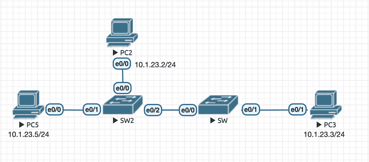
Figure 26: 实验环境
实验配置
----------------- SW ----------------------
en
conf t
hostname SW
no ip do lo
line con 0
 exec-timeout 0 0
 logging synchronous
 exit
int e0/0
 switchport mode access
 shutdown ! better to shutdown first
 switchport port-security ! have to add this config to enable port-security feature
 switchport port-security mac-address sticky
 no shutdown

----------------- SW2 ----------------------
en
conf t
hostname SW2
no ip do lo
line con 0
 exec-timeout 0 0
 logging synchronous
 exit
int e0/2
 switchport mode access ! not to send DTP
 no cdp enable ! not to send CDP
 no spanning-tree vlan 1 ! not to send STP

----------------- PC2 ----------------------
en
conf t
hostname PC2
no ip routing
no ip do lo
line con 0
 exec-timeout 0 0
 logging synchronous
 exit
int e0/0
 ip address 10.1.23.2 255.255.255.0
 no sh

----------------- PC3 ----------------------
en
conf t
hostname PC3
no ip routing
no ip do lo
line con 0
 exec-timeout 0 0
 logging synchronous
 exit
int e0/1
 ip address 10.1.23.3 255.255.255.0
 no sh

----------------- PC5 ----------------------
en
conf t
hostname PC5
no ip routing
no ip do lo
line con 0
 exec-timeout 0 0
 logging synchronous
 exit
int e0/0
 ip address 10.1.23.5 255.255.255.0
 no sh
PC2 和 PC5 谁第一个与 PC3 通信,谁就占据端口,后来者如果也尝试与 PC3 通信,则 SW e0/0 会触发 err-disable 。
7.1.2 Static CAM
基于源 MAC 限制 流量。
SW(confit)#mac address-table static aabb.cc00.2000 vlan 1 drop 6
7.1.3 Block UNKNOWN unicast/multicast 7
7.2 Anti VLAN attack
7.2.1 VACL
VACL 可以匹配 IP 或者 MAC 地址,并作出响应的动作 Forward 或是 Drop 。
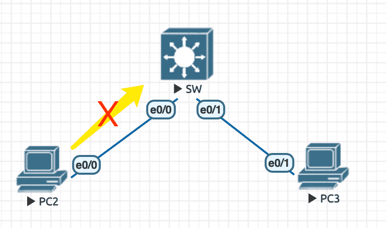
Figure 27: 实验环境
初始配置
----------------- SW ----------------------
en
conf t
hostname SW
no ip do lo
line con 0
  exec-timeout 0 0
  logging synchronous
  exit
vlan 100
  name MYVLAN100
  exit
int range e0/0,e0/1
  switchport access vlan 100
  switchport mode access
  spanning-tree portfast ! nice to have

----------------- PC2 ----------------------
en
conf t
hostname PC2
no ip do lo
line con 0
  exec-timeout 0 0
  logging synchronous
  exit
int e0/0
  ip address 100.1.1.2 255.255.255.0
  no sh

----------------- PC3 ----------------------
en
conf t
hostname PC3
no ip do lo
line con 0
  exec-timeout 0 0
  logging synchronous
  exit
int e0/1
  ip address 100.1.1.3 255.255.255.0
  no sh
基于 IP 的访问控制
----------------- SW ----------------------
en
conf t
hostname SW
no ip do lo
line con 0
  exec-timeout 0 0
  logging synchronous
  exit
vlan 100
  name MYVLAN100
  exit
int range e0/0,e0/1
  switchport access vlan 100
  switchport mode access
  spanning-tree portfast ! nice to have
  exit

ip access-list standard PC2
  permit 100.1.1.2
  exit
vlan access-map PC2_MAP 10
  match ip address PC2
  action drop
  exit
vlan filter PC2_MAP vlan-list 100
基于 MAC 的访问控制
----------------- SW ----------------------
en
conf t
hostname SW
no ip do lo
line con 0
  exec-timeout 0 0
  logging synchronous
  exit
vlan 100
  name MYVLAN100
  exit
int range e0/0,e0/1
  switchport access vlan 100
  switchport mode access
  spanning-tree portfast ! nice to have
  exit

mac access-list extended PC2_MAC
 permit host aabb.cc00.2000 any
 exit
vlan access-map PC2_ACCESS_MAP 10
 match mac address PC2_MAC
 action drop
 exit
vlan filter PC2_ACCESS_MAP vlan-list 100
7.2.2 PVLAN
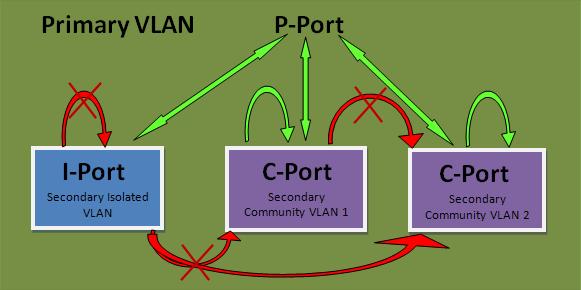
Figure 28: PVLAN 端口隔离
7.2.2.1 规则
- 一个主 VLAN 中 只能有一个 隔离子 VLAN , 可以有多个 Community 子 VLAN
- 隔离 VLAN 内的主机间不能相互访问,也不能和其他子 VLAN ,也不能和外部 VLAN 访问,只能访问混杂端口
- Community VLAN 内的主机间可以相互访问,可以和混杂端口访问,但不能访问其他子 VLAN ,也不能访问外部 VLAN
7.2.2.2 配置
配置步骤:
- VTP mode 设为 transparent
- 配置 Primary/Secondary VLAN 并进行关联 (
private-vlan association) - 将端口划入相应 VLAN (
switchport mode private-vlan promiscuous/host)
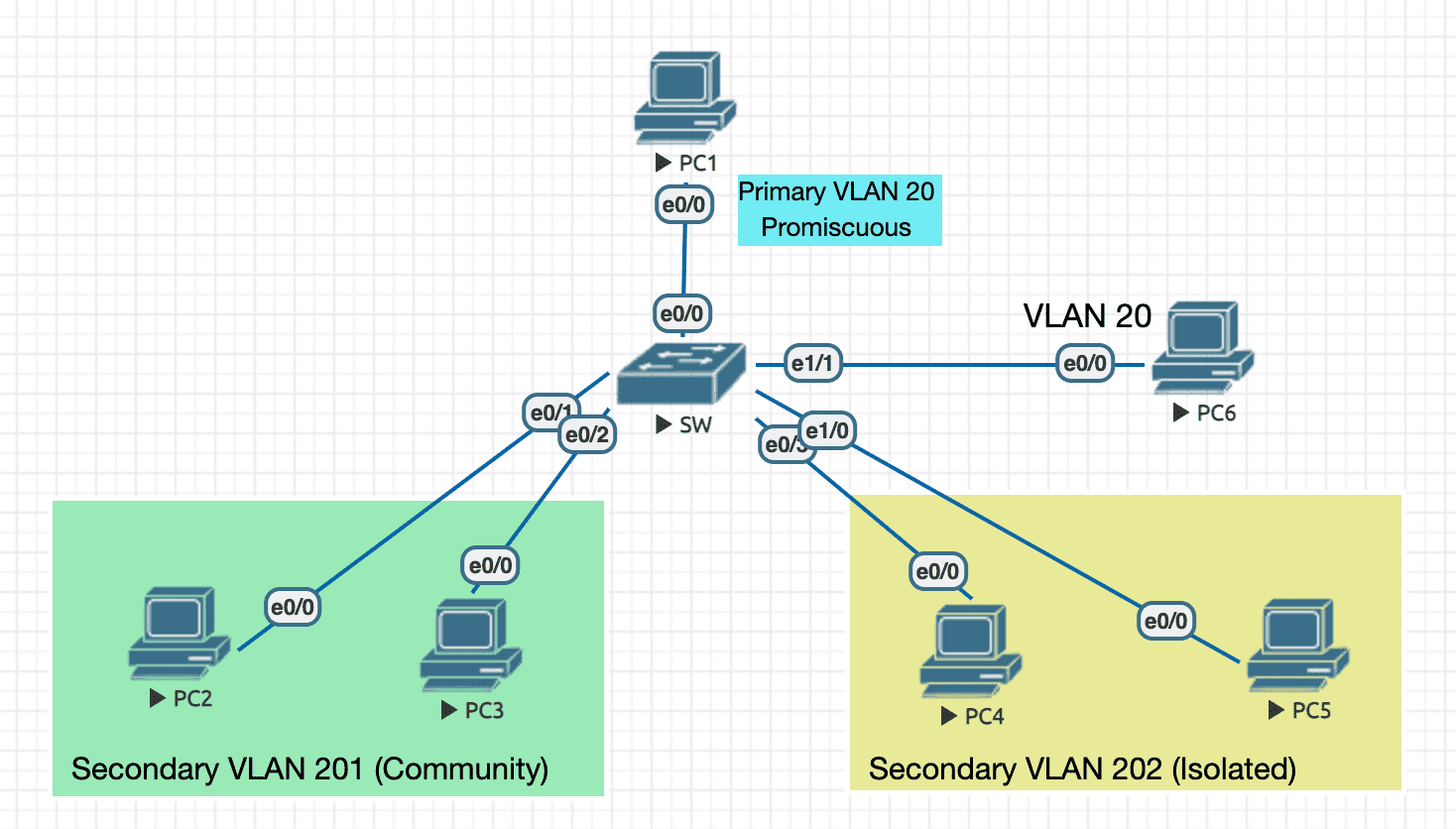
Figure 29: 实验环境
实验配置
----------------- SW ----------------------
en
conf t
hostname SW
ip routing
no ip do lo
line con 0
 exec-timeout 0 0
 logging synchronous
 exit
spanning-tree portfast edge default ! nice to have
vtp mode transparent ! must do this for pvlan

vlan 201
 name SECONDARY_COMMUNITY_VLAN_201
 private-vlan community
 exit
vlan 202
 name SECONDARY_ISOLATED_VLAN_202
 private-vlan isolated
 exit
vlan 20
 name PRIMARY_VLAN_20
 private-vlan primary
 private-vlan association 201,202 ! associate with secondary vlans
 exit
int vlan 20
 ip address 10.1.1.20 255.255.255.0
 private-vlan mapping 201,202 ! must have this, orelse only R1 can access svi
 no sh


int e0/0 ! R1
 switchport mode private-vlan promiscuous
 switchport private-vlan mapping 20 201,202 ! specify secondary vlans to which we need access
 exit
int range e0/1,e0/2 ! R2, R3
 switchport mode private-vlan host
 switchport private-vlan host-association 20 201
 exit
int range e0/3,e1/0 ! R4, R5
 switchport mode private-vlan host
 switchport private-vlan host-association 20 202
int e1/1 ! R6
 switchport mode access
 switchport access vlan 20 ! cannot access ports under primary/secondary vlan 20 actually


----------------- PC1 ----------------------
en
conf t
hostname PC1
no ip routing
no ip do lo
line con 0
 exec-timeout 0 0
 logging synchronous
 exit
int e0/0
 ip address 10.1.1.1 255.255.255.0
 no sh

----------------- PC2 ----------------------
en
conf t
hostname PC2
no ip routing
no ip do lo
line con 0
 exec-timeout 0 0
 logging synchronous
 exit
int e0/0
 ip address 10.1.1.2 255.255.255.0
 no sh

----------------- PC3 ----------------------
en
conf t
hostname PC3
no ip routing
no ip do lo
line con 0
 exec-timeout 0 0
 logging synchronous
 exit
int e0/0
 ip address 10.1.1.3 255.255.255.0
 no sh

----------------- PC4 ----------------------
en
conf t
hostname PC4
no ip routing
no ip do lo
line con 0
 exec-timeout 0 0
 logging synchronous
 exit
int e0/0
 ip address 10.1.1.4 255.255.255.0
 no sh

----------------- PC5 ----------------------
en
conf t
hostname PC5
no ip routing
no ip do lo
line con 0
 exec-timeout 0 0
 logging synchronous
 exit
int e0/0
 ip address 10.1.1.5 255.255.255.0
 no sh

----------------- PC6 ----------------------
en
conf t
hostname PC6
no ip routing
no ip do lo
line con 0
 exec-timeout 0 0
 logging synchronous
 exit
int e0/0
 ip address 10.1.1.6 255.255.255.0
 no sh
查看 pvlan 信息
SW#sh vlan private-vlan

Primary Secondary Type              Ports
------- --------- ----------------- ------------------------------------------
20      201       community         Et0/0, Et0/1, Et0/2
20      202       isolated          Et0/0, Et0/3, Et1/0
SW#sh int e0/0 switchport
Name: Et0/0
Switchport: Enabled
Administrative Mode: private-vlan promiscuous
Operational Mode: private-vlan promiscuous
Administrative Trunking Encapsulation: negotiate
Operational Trunking Encapsulation: native
Negotiation of Trunking: Off
Access Mode VLAN: 1 (default)
Trunking Native Mode VLAN: 1 (default)
Administrative Native VLAN tagging: enabled
Voice VLAN: none
Administrative private-vlan host-association: none
Administrative private-vlan mapping: 20 (PRIMARY_VLAN_20) 201 (SECONDARY_COMMUNITY_VLAN_201) 202 (SECONDARY_ISOLATED_VLAN_202)
Administrative private-vlan trunk native VLAN: none
Administrative private-vlan trunk Native VLAN tagging: enabled
Administrative private-vlan trunk encapsulation: dot1q
Administrative private-vlan trunk normal VLANs: none
Administrative private-vlan trunk associations: none
Administrative private-vlan trunk mappings: none
Operational private-vlan:
  20 (PRIMARY_VLAN_20) 201 (SECONDARY_COMMUNITY_VLAN_201) 202 (SECONDARY_ISOLATED_VLAN_202)
Trunking VLANs Enabled: ALL
Pruning VLANs Enabled: 2-1001
Capture Mode Disabled
Capture VLANs Allowed: ALL

Protected: false
Appliance trust: none
SW#sh int e0/1 switchport
Name: Et0/1
Switchport: Enabled
Administrative Mode: private-vlan host
Operational Mode: private-vlan host
Administrative Trunking Encapsulation: negotiate
Operational Trunking Encapsulation: native
Negotiation of Trunking: Off
Access Mode VLAN: 1 (default)
Trunking Native Mode VLAN: 1 (default)
Administrative Native VLAN tagging: enabled
Voice VLAN: none
Administrative private-vlan host-association: 20 (PRIMARY_VLAN_20) 201 (SECONDARY_COMMUNITY_VLAN_201)
Administrative private-vlan mapping: none
Administrative private-vlan trunk native VLAN: none
Administrative private-vlan trunk Native VLAN tagging: enabled
Administrative private-vlan trunk encapsulation: dot1q
Administrative private-vlan trunk normal VLANs: none
Administrative private-vlan trunk associations: none
Administrative private-vlan trunk mappings: none
Operational private-vlan:
  20 (PRIMARY_VLAN_20) 201 (SECONDARY_COMMUNITY_VLAN_201)
Trunking VLANs Enabled: ALL
Pruning VLANs Enabled: 2-1001
Capture Mode Disabled
Capture VLANs Allowed: ALL

Protected: false
Appliance trust: none
- PC6 不能与任何 PC 互访 (包括 SVI)
- PC1(promiscuous) 可以与除 PC6 以外的任何 PC 互访
- 如果没有
private-vlan mapping 201,202,SVI 默认只能与 PC1(promiscuous) 互访 - PC2 与 PC3 可以互访,但不能访问 VLAN 202 中的 PC
- VLAN 202 中的 PC 不能互访,与外界也不能互访
7.2.3 protected 8
protected 端口之间不能互访。
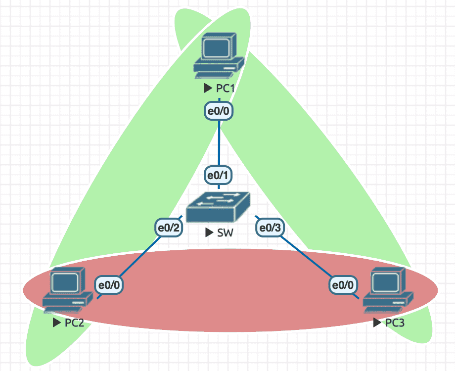
Figure 30: 实验环境
实验配置
----------------- SW ----------------------
en
conf t
hostname SW
no ip do lo
line con 0
 exec-timeout 0 0
 logging synchronous
 exit
spanning-tree portfast edge default ! nice to have
int e0/2 ! R2
 switchport protected
 exit
int e0/3 ! R3
 switchport protected
 exit
exit

----------------- PC1 ----------------------
en
conf t
hostname PC1
no ip routing
no ip do lo
line con 0
 exec-timeout 0 0
 logging synchronous
 exit
int e0/0
 ip address 10.1.1.1 255.255.255.0
 no sh

----------------- PC2 ----------------------
en
conf t
hostname PC2
no ip routing
no ip do lo
line con 0
 exec-timeout 0 0
 logging synchronous
 exit
int e0/0
 ip address 10.1.1.2 255.255.255.0
 no sh

----------------- PC3 ----------------------
en
conf t
hostname PC3
no ip routing
no ip do lo
line con 0
 exec-timeout 0 0
 logging synchronous
 exit
int e0/0
 ip address 10.1.1.3 255.255.255.0
 no sh
7.3 Anti Snoofing attack
7.3.1 DHCP Snooping
当部署了 DHCP Snooping 后,交换机上所有端口都会置为 untrusted 。
trusted 端口直连 DHCP 服务器,或是位于连接 DHCP 服务器的上行链路上。
- untrusted
- 接收 Discovery (host -> sw)
- 不发出 Discovery (sw -> host)
- 不接收 Offer (host -> sw)
- 发送 Offer (sw -> host)
- trusted
- 接收/发送任何 DHCP 消息
部署 DHCP Snooping :
1) ip dhcp snooping                      // 开启 DHCP Snooping 开关
2) ip dhcp snooping vlan 1               // 指定 vlan
3) ip dhcp snooping trust                // 配置连接合法 DHCP Server 的接口与交换机之间的 trunk 接口为信任接口
4) ip dhcp relay information trust-all   // 在 cisco DHCP Server 上,设置信任 DHCP 消息 (cisco 交换机会在 Discovery 消息里添加 optiona82 ,相当于篡改了消息,需要此条命令允许这种行为)
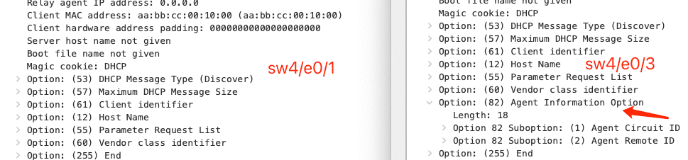
Figure 31: trust 接口发出的 DHCP Discovery 会带上 Option82
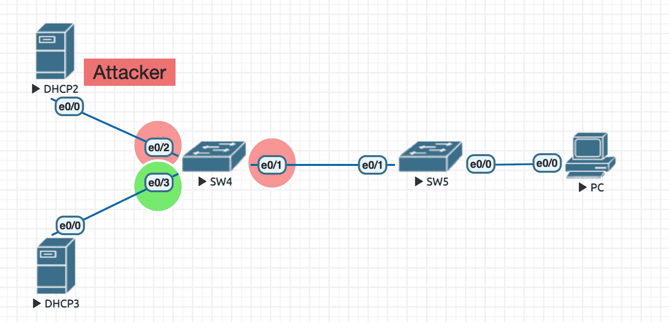
Figure 32: 实验环境
实验配置
----------------- SW4 ----------------------
en
conf t
hostname SW4
no ip do lo
line con 0
 exec-timeout 0 0
 logging synchronous
 exit
ip dhcp snooping ! must have this
ip dhcp snooping vlan 1 ! all ports will be untrusted when this line takes effect
int e0/3
 ip dhcp snooping trust
 exit
exit

----------------- DHCP2 ----------------------
en
debug ip packet detail
conf t
hostname DHCP2
no ip do lo
line con 0
 exec-timeout 0 0
 logging synchronous
 exit
ip dhcp pool MYPOOL
 network 2.2.2.0 /24
 exit
int e0/0
 ip address 2.2.2.2 255.255.255.0
 no sh
 exit
exit

----------------- DHCP3 ----------------------
en
debug ip packet detail
conf t
hostname DHCP3
no ip do lo
line con 0
 exec-timeout 0 0
 logging synchronous
 exit
ip dhcp pool MYPOOL
 network 3.3.3.0 /24
 exit
ip dhcp relay information trust-all ! have to add this after switch port set to trusted. let dhcp server accept option82
int e0/0
 ip address 3.3.3.3 255.255.255.0
 no sh
 exit
exit
查看绑定信息
SW4#sh ip dhcp snooping binding
MacAddress          IpAddress        Lease(sec)  Type           VLAN  Interface
------------------  ---------------  ----------  -------------  ----  --------------------
AA:BB:CC:00:10:00   3.3.3.2          85408       dhcp-snooping   1     Ethernet0/1
Total number of bindings: 1
SW4#sh ip dhcp snooping
Switch DHCP snooping is enabled
Switch DHCP gleaning is disabled
DHCP snooping is configured on following VLANs:
1
DHCP snooping is operational on following VLANs:
1
DHCP snooping is configured on the following L3 Interfaces:

Insertion of option 82 is enabled
   circuit-id default format: vlan-mod-port
   remote-id: aabb.cc00.4000 (MAC)
Option 82 on untrusted port is not allowed
Verification of hwaddr field is enabled
Verification of giaddr field is enabled
DHCP snooping trust/rate is configured on the following Interfaces:

Interface                  Trusted    Allow option    Rate limit (pps)
-----------------------    -------    ------------    ----------------
Ethernet0/3                yes        yes             unlimited
  Custom circuit-ids:
7.3.2 IP 源保护 9
该功能配置于 untrusted 接口。
未通过 DHCP 获得 IP 前,即交换机没有向 client 转发过 Offer (没有形成 dhcp snooping binding 表),
端口上接收到的 client 数据都会被丢弃。即检查数据包的 src ip 是否出现在 dhcp snooping binding 中,如出现的,就是合法的。
ip source binding 0011.0022.0033 vlan 1 192.168.1.100 interface e0/1  # 静态绑定,同时 DHCP Snooping 方式建立的 binding 是动态绑定

show ip dhcp snooping binding      # 查看通过 DHCP Snooping 动态形成的绑定表
show ip source binding             # 查看动态绑定表和静态绑定表

SW(config-if)#ip verify source     # 在接口上开启源保护,检测从此接口收到的数据包源 IP 地址
7.3.2.1 MAC 源保护
可以在 IP 源保护的基础上增加 MAC 源保护的功能:
int e0/1
 switchport mode access
 switchport port-security
 ip verify source port-security   ! 会检查从此接口收的的数据包的源 IP 与源 MAC
!
7.3.3 Dynamic ARP Inspection 10
DAI 定义两种端口状态:
untrusted
对于收到的 ARP Request (包括 Gratuitous ARP) ,会基于 DHCP Snooping Binding 表进行 IP/MAC 关联检查
trusted
正常收发
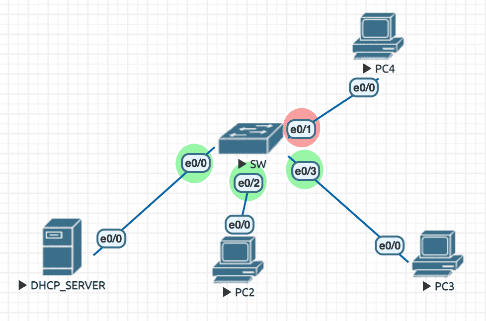
Figure 33: 实验环境
实验配置
----------------- PC2 ----------------------
en
conf t
hostname PC2
no ip do lo
line con 0
 exec-timeout 0 0
 logging synchronous
 exit
int e0/0
 ip address dhcp
 no sh
 exit
exit

----------------- PC3 ----------------------
en
conf t
hostname PC3
no ip do lo
line con 0
 exec-timeout 0 0
 logging synchronous
 exit
int e0/0
 ip address dhcp
 no sh
 exit
exit

----------------- PC4 ----------------------
en
conf t
hostname PC4
no ip do lo
line con 0
 exec-timeout 0 0
 logging synchronous
 exit
int e0/0
 ip address 10.1.1.100 255.255.255.0
 no sh
 exit
exit

----------------- SW ----------------------
en
conf t
hostname SW
no ip do lo
line con 0
 exec-timeout 0 0
 logging synchronous
 exit
ip dhcp snooping ! must have this
ip dhcp snooping vlan 1
int e0/0
 ip dhcp snooping trust
 exit
int range e0/0,e0/2,e0/3
 ip arp inspection trust
ip arp inspection vlan 1
exit

----------------- DHCP_SERVER ----------------------
en
conf t
hostname DHCP_SERVER
no ip do lo
line con 0
 exec-timeout 0 0
 logging synchronous
 exit
ip dhcp pool MYPOOL
 network 10.1.1.0 /24
 exit
ip dhcp relay information trust-all ! have to add this after switch port set to trusted. let dhcp server accept option82
int e0/0
 ip address 10.1.1.1 255.255.255.0
 no sh
 exit
exit
信息查看
SW#sh ip dhcp snooping binding ! 绑定表
MacAddress          IpAddress        Lease(sec)  Type           VLAN  Interface
------------------  ---------------  ----------  -------------  ----  --------------------
AA:BB:CC:00:30:00   10.1.1.6         85495       dhcp-snooping   1     Ethernet0/3
AA:BB:CC:00:20:00   10.1.1.5         85468       dhcp-snooping   1     Ethernet0/2
Total number of bindings: 2
SW#sh ip arp inspection interfaces

 Interface        Trust State     Rate (pps)    Burst Interval
 ---------------  -----------     ----------    --------------
 Et0/0            Trusted               None               N/A
 Et0/1            Untrusted               15                 1
 Et0/2            Trusted               None               N/A
 Et0/3            Trusted               None               N/A
告警信息
当 PC4 尝试 ping PC2/PC3 :
SW#
*Jul 15 11:08:24.228: %SW_DAI-4-DHCP_SNOOPING_DENY: 1 Invalid ARPs (Req) on Et0/1, vlan 1.([aabb.cc00.4000/10.1.1.100/0000.0000.0000/10.1.1.5/13:08:23 EET Thu Jul 15 2021])
SW#
7.4 Telnet/SSH
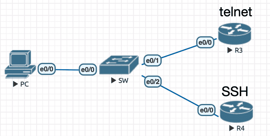
Figure 34: 实验环境
实验配置
----------------- PC ----------------------
en
conf t
hostname PC
no ip do lo
line con 0
 exec-timeout 0 0
 logging synchronous
 exit
int e0/0
 ip address 10.1.1.1 255.255.255.0
 no sh
 exit
exit

----------------- R3 ----------------------
en
conf t
hostname R3
no ip do lo
line con 0
 logging synchronous
 exit
int e0/0
 ip address 10.1.1.3 255.255.255.0
 no sh
 exit
username cisco password 0 cisco
line vty 0 4
 login local ! 'local' is meant to use the local database for authentication
 transport input telnet
 exit
end

----------------- R4 ----------------------
en
conf t
hostname R4
no ip do lo
line con 0
 exec-timeout 0 0
 logging synchronous
 exit
int e0/0
 ip address 10.1.1.4 255.255.255.0
 no sh
 exit
ip domain name cisco.com
crypto key generate rsa general-keys modulus 1024
ip ssh time-out 120
ip ssh authentication-retries 4
username cisco password 0 cisco
line vty 0 4
 login local ! 'local' is meant to use the local database for authentication
 transport input ssh
 exit
exit
尝试登陆
PC#telnet 10.1.1.3
Trying 10.1.1.3 ... Open

User Access Verification

Username: cisco
Password:
R3>exit

[Connection to 10.1.1.3 closed by foreign host]
PC#ssh -l cisco 10.1.1.4
Password:
R4>exit

[Connection to 10.1.1.4 closed by foreign host]