组播
{Back to Index}
Table of Contents
1 概述
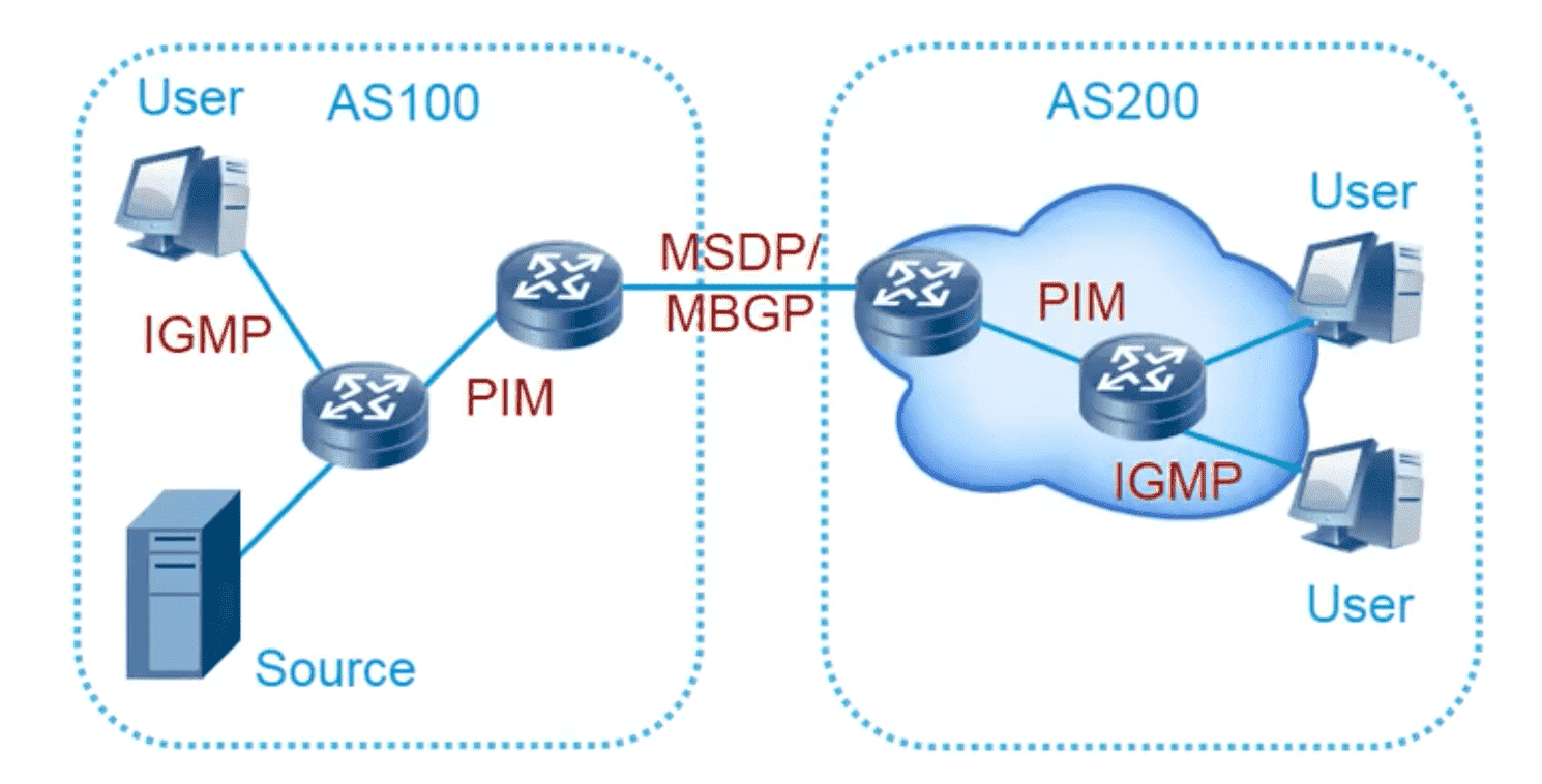
Figure 1: 组播协议概览
PIM 指的是对路由协议(IGP)没有要求的组播协议,DVMRP(IGP 必须基于跳数)和 MOSPF 9LSA6) 已淘汰。
IGMP 用于连接组播的终端(用户)和组播网络。
组播网络中的主要角色:
- 源设备(发送组播数据设备)
- 接收组播数据的设备
- 组播路由器网络
组播流通常情况不允许负载均衡,否则下游设备会出现多个 Incoming Interface 这是不允许的, 只能有一个 iif 。
2 IGMP
IGMP 运行于主机和与主机直连的组播路由器之间,它的工作机制:
- 接收者主机向所在共享网络报告组成员关系
- 查询器周期性向共享网段发送组成员查询消息
- 接收者主机收到查询消息后进行相应以报告成员关系
- 网段中的组播路由器依据接收到的相应来刷新组成员的存在信息
IGMP v1-v3 区别:
- v1 定义了基本的组成员查询和报告过程
- v2 增加了成员快速离开的机制
- v3 成员可以指定接收或指定不接收某些组播源的数据
2.1 Snooping
截获 IGMP Report 报文并映射交换机端口与组播地址,以解决交换机 组播泛洪问题 。

Figure 2: 实验环境
实验配置
----------------- SW ----------------------
en
conf t
hostname SW
no ip do lo
line con 0
  exec-timeout 0 0
  logging synchronous
exit
ip igmp snooping ! enable snooping for all vlans, check by: sh ip igmp snooping
----------------- R1 ----------------------
en
conf t
hostname R1
no ip do lo
line con 0
  exec-timeout 0 0
  logging synchronous
exit
ip multicast-routing ! enable multicast
int lo0
  ip address 1.1.1.1 255.255.255.255
int e0/0
  ip address 12.1.1.1 255.255.255.0
  ip pim sparse-mode ! have to specify mode when using multicast
  no sh
----------------- PC2 ----------------------
en
conf t
hostname PC2
no ip do lo
line con 0
  exec-timeout 0 0
  logging synchronous
exit
no ip routing
ip default-gateway 12.1.1.1
int lo0
  ip address 2.2.2.2 255.255.255.255
int e0/1
  ip address 12.1.1.2 255.255.255.0
  ip igmp join-group 224.1.1.1
  no sh
查看 Snooping 映射表
SW#sh ip igmp snooping groups
Vlan      Group                    Version     Port List
---------------------------------------------------------
1         224.0.1.40               v2          Et0/0 ! 实现相关,无需关心
1         224.1.1.1                v2          Et0/1 ! 组播地址 224.1.1.1 与接口 e0/1 绑定
3 组播转发
3.1 组播路由思想
单播路由关心数据包到哪里去,而 组播路由 更 关心的是数据包从哪里来 ,如下图所示, R3 必须通过多播路由表决定到底接收那边的流量 以 防止接收重复包 。
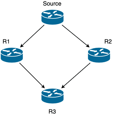
组播入接口通常称为 RPF 接口 (Reverse Path Forwarding) ,一个路由器只有一个 RPF 接口,所谓的反向 (Reverse) 是利用单播路由来做反向路径检查。
RPF 另一个意义在于避免发生 forwarding loop 。
3.2 RPF 检查
假设从源(假设IP为S)收到组播数据,入接口为 IF ,那么路由器上必须存在去往 S 的单播路由,且出接口也必须是 IF 。
3.3 RPF 接口确定
3.3.1 手工指定静态组播路由
指定组播静态路由的作用仅仅是用于人为确定 RPF 接口,并不影响组播转发。
以图 4 为例,假设想手工指定 R2 的 e0/1 作为针对源 10.1.13.3 的 RPF 接口:
初始状态
R2#sh ip rpf 10.1.13.3
RPF information for ? (10.1.13.3)
  RPF interface: Serial1/0
  RPF neighbor: ? (10.1.21.1)
  RPF route/mask: 10.1.13.0/24
  RPF type: unicast (ospf 110)
  Doing distance-preferred lookups across tables
  RPF topology: ipv4 multicast base, originated from ipv4 unicast base
手工指定静态组播路由
R2(config)#ip mroute ?
  A.B.C.D  Source address
  vrf      Select VPN Routing/Forwarding instance

R2(config)#ip mroute 10.1.13.3 255.255.255.255 10.1.12.1
路由检查
R2#sh ip rpf 10.1.13.3
RPF information for ? (10.1.13.3)
  RPF interface: Ethernet0/1
  RPF neighbor: ? (10.1.12.1)
  RPF route/mask: 10.1.13.3/32
  RPF type: multicast (static)
  Doing distance-preferred lookups across tables
  RPF topology: ipv4 multicast base

R2#sh ip mroute 239.1.1.1
IP Multicast Routing Table
Flags: D - Dense, S - Sparse, B - Bidir Group, s - SSM Group, C - Connected,
       L - Local, P - Pruned, R - RP-bit set, F - Register flag,
       T - SPT-bit set, J - Join SPT, M - MSDP created entry, E - Extranet,
       X - Proxy Join Timer Running, A - Candidate for MSDP Advertisement,
       U - URD, I - Received Source Specific Host Report,
       Z - Multicast Tunnel, z - MDT-data group sender,
       Y - Joined MDT-data group, y - Sending to MDT-data group,
       G - Received BGP C-Mroute, g - Sent BGP C-Mroute,
       N - Received BGP Shared-Tree Prune, n - BGP C-Mroute suppressed,
       Q - Received BGP S-A Route, q - Sent BGP S-A Route,
       V - RD & Vector, v - Vector, p - PIM Joins on route,
       x - VxLAN group
Outgoing interface flags: H - Hardware switched, A - Assert winner, p - PIM Join
 Timers: Uptime/Expires
 Interface state: Interface, Next-Hop or VCD, State/Mode

(*, 239.1.1.1), 00:05:17/stopped, RP 0.0.0.0, flags: DC
  Incoming interface: Null, RPF nbr 0.0.0.0
  Outgoing interface list:
    Ethernet0/0, Forward/Dense, 00:04:49/stopped
    Serial1/0, Forward/Dense, 00:05:17/stopped
    Ethernet0/1, Forward/Dense, 00:05:17/stopped

(10.1.13.3, 239.1.1.1), 00:05:17/00:01:31, flags: T
  Incoming interface: Ethernet0/1, RPF nbr 10.1.12.1, Mroute
  Outgoing interface list:
    Serial1/0, Prune/Dense, 00:02:31/00:00:30
    Ethernet0/0, Forward/Dense, 00:04:49/stopped

R2#sh ip route 10.1.13.3
Routing entry for 10.1.13.0/24
  Known via "ospf 110", distance 110, metric 74, type intra area
  Last update from 10.1.21.1 on Serial1/0, 00:06:37 ago ! 单播路由出接口仍然是 s1/0
  Routing Descriptor Blocks:
  * 10.1.21.1, from 1.1.1.1, 00:06:37 ago, via Serial1/0
      Route metric is 74, traffic share count is 1

R2#sh ip mroute static
Mroute: 10.1.13.3/32, RPF neighbor: 10.1.12.1, distance: 1 ! 本质还是 AD 的比较
3.3.2 AD 越小优先
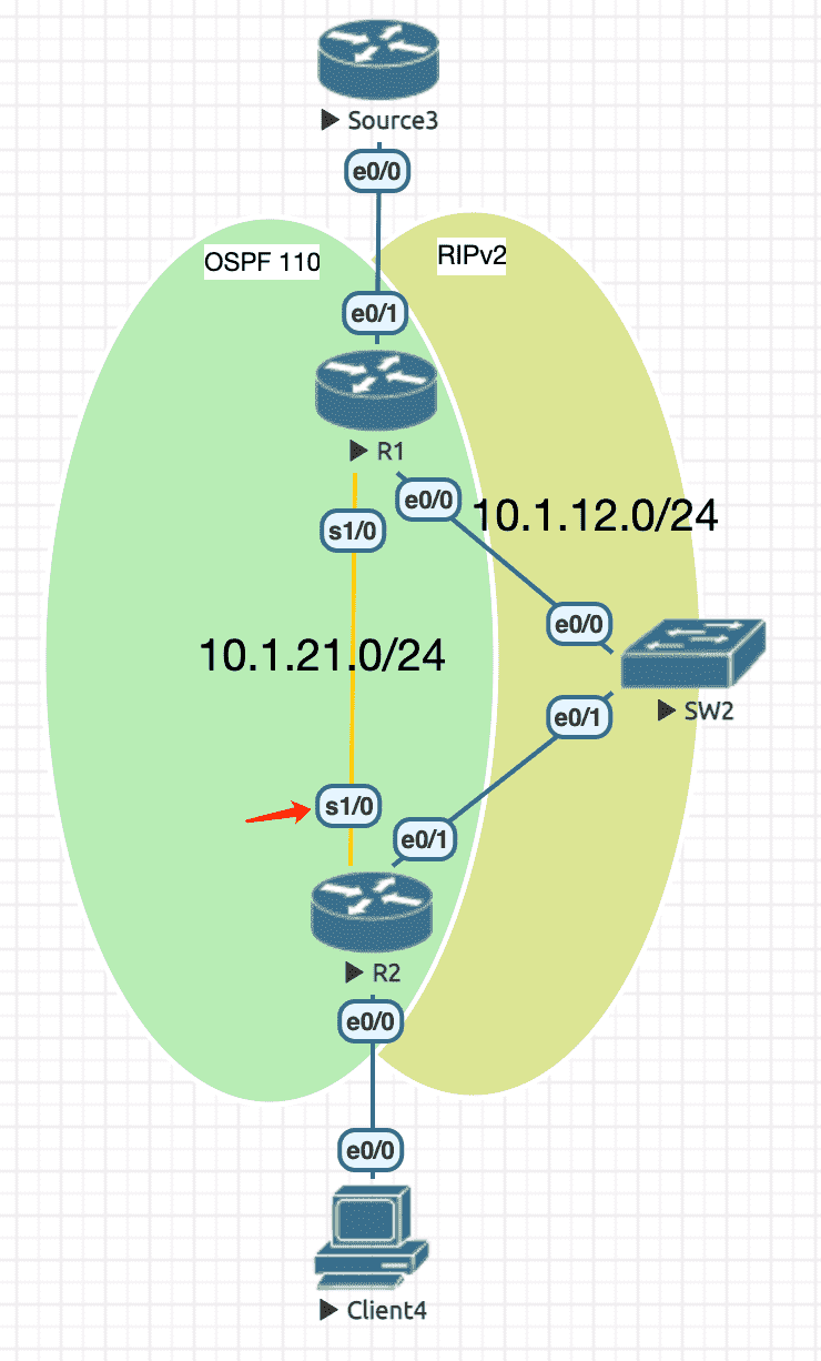
Figure 4: 组播源地址分别从 OSPF 和 RIPv2 学习到
实验配置
----------------- Source3 ----------------------
en
conf t
hostname Source3
no ip do lo
line con 0
  exec-timeout 0 0
  logging synchronous
exit
ip multicast-routing ! enable multicast
int lo0
  ip address 3.3.3.3 255.255.255.255
int e0/0
  ip address 10.1.13.3 255.255.255.0
  ip pim dense-mode ! have to specify mode when using multicast
  no sh
----------------- R1 ----------------------
en
conf t
hostname R1
no ip do lo
line con 0
  exec-timeout 0 0
  logging synchronous
exit
ip multicast-routing ! enable multicast
int lo0
  ip address 1.1.1.1 255.255.255.255
int e0/0
  ip address 10.1.12.1 255.255.255.0
  ip pim dense-mode ! have to specify mode when using multicast
  no sh
int e0/1
  ip address 10.1.13.1 255.255.255.0
  ip pim dense-mode ! have to specify mode when using multicast
  no sh
int s1/0
  ip address 10.1.21.1 255.255.255.0
  ip pim dense-mode ! have to specify mode when using multicast
  no sh
router ospf 110
  router-id 1.1.1.1
  network 10.1.21.1 0.0.0.0 area 0
  network 10.1.13.1 0.0.0.0 area 0
router rip
  version 2
  no auto-summary
  network 10.1.12.1
  network 10.1.13.1
----------------- R2 ----------------------
en
conf t
hostname R2
no ip do lo
line con 0
  exec-timeout 0 0
  logging synchronous
exit
ip multicast-routing ! enable multicast
int lo0
  ip address 2.2.2.2 255.255.255.255
int e0/0
  ip address 10.1.24.2 255.255.255.0
  ip pim dense-mode ! have to specify mode when using multicast
  no sh
int e0/1
  ip address 10.1.12.2 255.255.255.0
  ip pim dense-mode ! have to specify mode when using multicast
  no sh
int s1/0
  ip address 10.1.21.2 255.255.255.0
  ip pim dense-mode ! have to specify mode when using multicast
  no sh
router ospf 110
  router-id 2.2.2.2
  network 10.1.21.2 0.0.0.0 area 0
  network 10.1.24.2 0.0.0.0 area 0
router rip
  version 2
  no auto-summary
  network 10.1.12.2
  network 10.1.24.2
----------------- Client4 ----------------------
en
conf t
hostname Client4
no ip do lo
line con 0
  exec-timeout 0 0
  logging synchronous
exit
no ip routing
ip default-gateway 10.1.24.2
int e0/0
  ip address 10.1.24.4 255.255.255.0
  ip igmp join-group 239.1.1.1
  no sh
RPF 检查
R2#sh ip route
Codes: L - local, C - connected, S - static, R - RIP, M - mobile, B - BGP
       D - EIGRP, EX - EIGRP external, O - OSPF, IA - OSPF inter area
       N1 - OSPF NSSA external type 1, N2 - OSPF NSSA external type 2
       E1 - OSPF external type 1, E2 - OSPF external type 2
       i - IS-IS, su - IS-IS summary, L1 - IS-IS level-1, L2 - IS-IS level-2
       ia - IS-IS inter area, * - candidate default, U - per-user static route
       o - ODR, P - periodic downloaded static route, H - NHRP, l - LISP
       a - application route
       + - replicated route, % - next hop override, p - overrides from PfR

Gateway of last resort is not set

      2.0.0.0/32 is subnetted, 1 subnets
C        2.2.2.2 is directly connected, Loopback0
      10.0.0.0/8 is variably subnetted, 7 subnets, 2 masks
C        10.1.12.0/24 is directly connected, Ethernet0/1
L        10.1.12.2/32 is directly connected, Ethernet0/1
O        10.1.13.0/24 [110/74] via 10.1.21.1, 00:15:30, Serial1/0
C        10.1.21.0/24 is directly connected, Serial1/0
L        10.1.21.2/32 is directly connected, Serial1/0
C        10.1.24.0/24 is directly connected, Ethernet0/0
L        10.1.24.2/32 is directly connected, Ethernet0/0
R2#sh ip rpf 10.1.13.3
RPF information for ? (10.1.13.3)
  RPF interface: Serial1/0
  RPF neighbor: ? (10.1.21.1)
  RPF route/mask: 10.1.13.0/24
  RPF type: unicast (ospf 110)
  Doing distance-preferred lookups across tables
  RPF topology: ipv4 multicast base, originated from ipv4 unicast base
3.3.3 Metric 越小优先
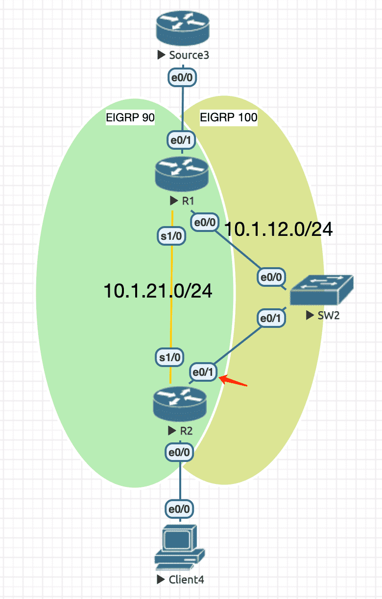
Figure 5: 组播源的 metric 值不同
实验配置
----------------- Source3 ----------------------
en
conf t
hostname Source3
no ip do lo
line con 0
  exec-timeout 0 0
  logging synchronous
exit
ip multicast-routing ! enable multicast
int lo0
  ip address 3.3.3.3 255.255.255.255
int e0/0
  ip address 10.1.13.3 255.255.255.0
  ip pim dense-mode ! have to specify mode when using multicast
  no sh
----------------- R1 ----------------------
en
conf t
hostname R1
no ip do lo
line con 0
  exec-timeout 0 0
  logging synchronous
exit
ip multicast-routing ! enable multicast
int lo0
  ip address 1.1.1.1 255.255.255.255
int e0/0
  ip address 10.1.12.1 255.255.255.0
  ip pim dense-mode ! have to specify mode when using multicast
  no sh
int e0/1
  ip address 10.1.13.1 255.255.255.0
  ip pim dense-mode ! have to specify mode when using multicast
  no sh
int s1/0
  ip address 10.1.21.1 255.255.255.0
  ip pim dense-mode ! have to specify mode when using multicast
  no sh
router eigrp 90
  network 10.1.21.1 0.0.0.0
  network 10.1.13.1 0.0.0.0
router eigrp 100
  network 10.1.12.1 0.0.0.0
  network 10.1.13.1 0.0.0.0

----------------- R2 ----------------------
en
conf t
hostname R2
no ip do lo
line con 0
  exec-timeout 0 0
  logging synchronous
exit
ip multicast-routing ! enable multicast
int lo0
  ip address 2.2.2.2 255.255.255.255
int e0/0
  ip address 10.1.24.2 255.255.255.0
  ip pim dense-mode ! have to specify mode when using multicast
  no sh
int e0/1
  ip address 10.1.12.2 255.255.255.0
  ip pim dense-mode ! have to specify mode when using multicast
  no sh
int s1/0
  ip address 10.1.21.2 255.255.255.0
  ip pim dense-mode ! have to specify mode when using multicast
  no sh
router eigrp 90
  network 10.1.21.2 0.0.0.0
  network 10.1.24.2 0.0.0.0
router eigrp 100
  network 10.1.12.2 0.0.0.0
  network 10.1.24.2 0.0.0.0

----------------- Client4 ----------------------
en
conf t
hostname Client4
no ip do lo
line con 0
  exec-timeout 0 0
  logging synchronous
exit
no ip routing
ip default-gateway 10.1.24.2
int e0/0
  ip address 10.1.24.4 255.255.255.0
  ip igmp join-group 239.1.1.1
  no sh
RPF 检查
R2#sh ip route
Codes: L - local, C - connected, S - static, R - RIP, M - mobile, B - BGP
       D - EIGRP, EX - EIGRP external, O - OSPF, IA - OSPF inter area
       N1 - OSPF NSSA external type 1, N2 - OSPF NSSA external type 2
       E1 - OSPF external type 1, E2 - OSPF external type 2
       i - IS-IS, su - IS-IS summary, L1 - IS-IS level-1, L2 - IS-IS level-2
       ia - IS-IS inter area, * - candidate default, U - per-user static route
       o - ODR, P - periodic downloaded static route, H - NHRP, l - LISP
       a - application route
       + - replicated route, % - next hop override, p - overrides from PfR

Gateway of last resort is not set

      2.0.0.0/32 is subnetted, 1 subnets
C        2.2.2.2 is directly connected, Loopback0
      10.0.0.0/8 is variably subnetted, 7 subnets, 2 masks
C        10.1.12.0/24 is directly connected, Ethernet0/1
L        10.1.12.2/32 is directly connected, Ethernet0/1
D        10.1.13.0/24 [90/307200] via 10.1.12.1, 00:01:38, Ethernet0/1
C        10.1.21.0/24 is directly connected, Serial1/0
L        10.1.21.2/32 is directly connected, Serial1/0
C        10.1.24.0/24 is directly connected, Ethernet0/0
L        10.1.24.2/32 is directly connected, Ethernet0/0
R2#sh ip rpf 10.1.13.3
RPF information for ? (10.1.13.3)
  RPF interface: Ethernet0/1
  RPF neighbor: ? (10.1.12.1)
  RPF route/mask: 10.1.13.0/24
  RPF type: unicast (eigrp 100)
  Doing distance-preferred lookups across tables
  RPF topology: ipv4 multicast base, originated from ipv4 unicast base
3.3.4 IP 越大优先
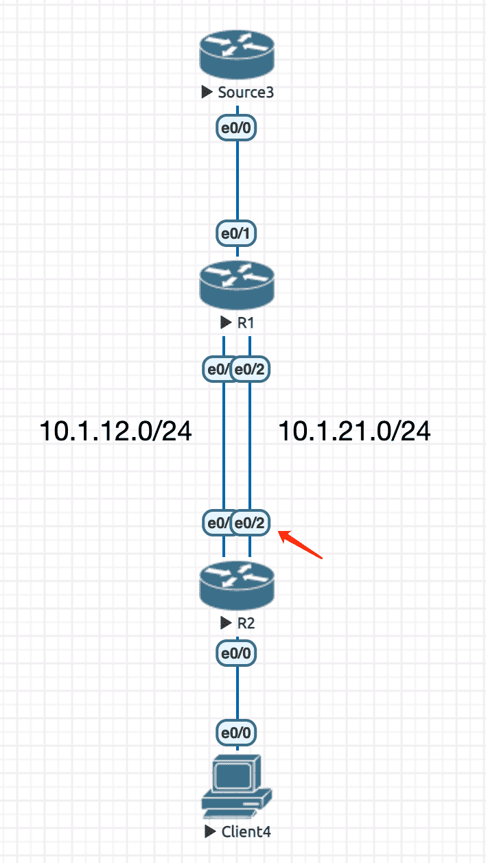
Figure 6: 手工指定两条负载均衡的静态路由
实验配置
----------------- Source3 ----------------------
en
conf t
hostname Source3
no ip do lo
line con 0
  exec-timeout 0 0
  logging synchronous
exit
ip multicast-routing ! enable multicast
int lo0
  ip address 3.3.3.3 255.255.255.255
int e0/0
  ip address 10.1.13.3 255.255.255.0
  ip pim dense-mode ! have to specify mode when using multicast
  no sh
----------------- R1 ----------------------
en
conf t
hostname R1
no ip do lo
line con 0
  exec-timeout 0 0
  logging synchronous
exit
ip multicast-routing ! enable multicast
int lo0
  ip address 1.1.1.1 255.255.255.255
int e0/0
  ip address 10.1.12.1 255.255.255.0
  ip pim dense-mode ! have to specify mode when using multicast
  no sh
int e0/1
  ip address 10.1.13.1 255.255.255.0
  ip pim dense-mode ! have to specify mode when using multicast
  no sh
int e0/2
  ip address 10.1.21.1 255.255.255.0
  ip pim dense-mode ! have to specify mode when using multicast
  no sh
router eigrp 90
  network 10.1.21.1 0.0.0.0
router eigrp 100
  network 10.1.12.1 0.0.0.0

----------------- R2 ----------------------
en
conf t
hostname R2
no ip do lo
line con 0
  exec-timeout 0 0
  logging synchronous
exit
ip multicast-routing ! enable multicast
int lo0
  ip address 2.2.2.2 255.255.255.255
int e0/0
  ip address 10.1.24.2 255.255.255.0
  ip pim dense-mode ! have to specify mode when using multicast
  no sh
int e0/1
  ip address 10.1.12.2 255.255.255.0
  ip pim dense-mode ! have to specify mode when using multicast
  no sh
int e0/2
  ip address 10.1.21.2 255.255.255.0
  ip pim dense-mode ! have to specify mode when using multicast
  no sh
router eigrp 90
  network 10.1.21.2 0.0.0.0
  network 10.1.24.2 0.0.0.0
router eigrp 100
  network 10.1.12.2 0.0.0.0
  network 10.1.24.2 0.0.0.0
  exit
ip route 10.1.13.3 255.255.255.255 10.1.12.1
ip route 10.1.13.3 255.255.255.255 10.1.21.1
----------------- Client4 ----------------------
en
conf t
hostname Client4
no ip do lo
line con 0
  exec-timeout 0 0
  logging synchronous
exit
no ip routing
ip default-gateway 10.1.24.2
int e0/0
  ip address 10.1.24.4 255.255.255.0
  ip igmp join-group 239.1.1.1
  no sh
RPF 检查
R2#sh ip route
Codes: L - local, C - connected, S - static, R - RIP, M - mobile, B - BGP
       D - EIGRP, EX - EIGRP external, O - OSPF, IA - OSPF inter area
       N1 - OSPF NSSA external type 1, N2 - OSPF NSSA external type 2
       E1 - OSPF external type 1, E2 - OSPF external type 2
       i - IS-IS, su - IS-IS summary, L1 - IS-IS level-1, L2 - IS-IS level-2
       ia - IS-IS inter area, * - candidate default, U - per-user static route
       o - ODR, P - periodic downloaded static route, H - NHRP, l - LISP
       a - application route
       + - replicated route, % - next hop override, p - overrides from PfR

Gateway of last resort is not set

      2.0.0.0/32 is subnetted, 1 subnets
C        2.2.2.2 is directly connected, Loopback0
      10.0.0.0/8 is variably subnetted, 7 subnets, 2 masks
C        10.1.12.0/24 is directly connected, Ethernet0/1
L        10.1.12.2/32 is directly connected, Ethernet0/1
S        10.1.13.3/32 [1/0] via 10.1.21.1
                      [1/0] via 10.1.12.1
C        10.1.21.0/24 is directly connected, Ethernet0/2
L        10.1.21.2/32 is directly connected, Ethernet0/2
C        10.1.24.0/24 is directly connected, Ethernet0/0
L        10.1.24.2/32 is directly connected, Ethernet0/0
R2#sh ip rpf 10.1.13.3
RPF information for ? (10.1.13.3)
  RPF interface: Ethernet0/2
  RPF neighbor: ? (10.1.21.1)
  RPF route/mask: 10.1.13.3/32
  RPF type: unicast (static)
  Doing distance-preferred lookups across tables
  RPF topology: ipv4 multicast base, originated from ipv4 unicast base
4 源树(SPT)与共享树(RPT)
4.1 源树
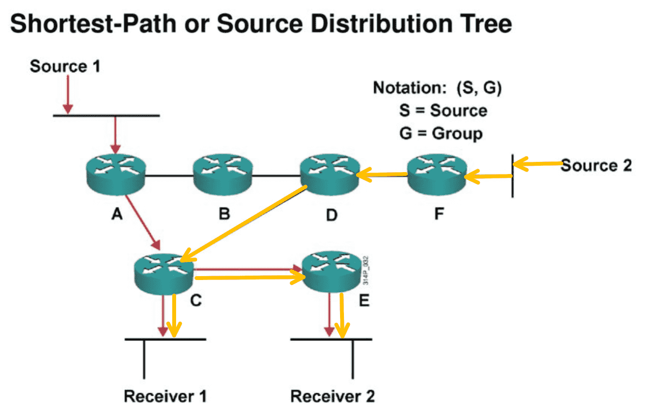
Figure 7: Tree is per source (图中两个源属于同一个组播组)
以源为根,接收者为叶构成了源树。源树的优点是路径是最优的,缺点在于途经的路由器针对每个源都要保存组播路由表项(消耗资源)。
该模式常用于 dense 模式中。
4.2 共享树
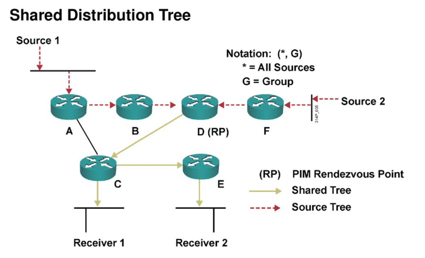
Figure 8: 图中两个源属于同一个组播组
RP 与最后一条路由器之间形成共享树,路径上的路由器只保存 (*,G) 组播表项(节省了资源消耗)。
源与 RP 之间仍然是以源树存在,造成源与接收者之间的路径未必是最优的。
这种结构其实是 两种树的结合 ,常用于 sparse 模式。
5 Dense-Mode
5.1 原理
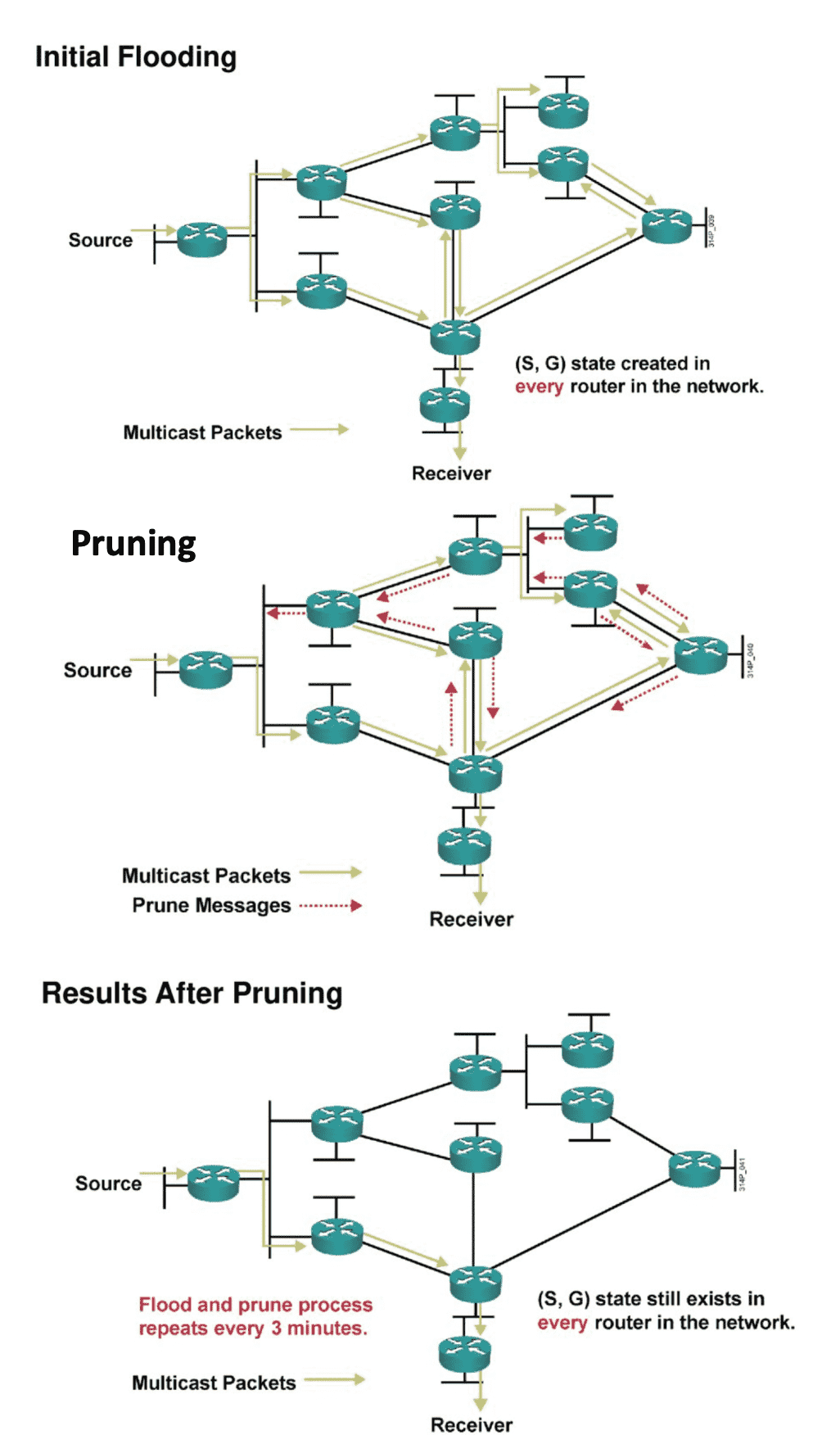
Figure 9: dense mode 三部曲
- 当组播源发送的组播数据时,一开始会在全网内扩散,当 PIM 路由器接收到组播数据,根据 单播路由表 进行 RPF 检查通过后(不通过的话就直接丢弃数据),就会在该路由器上创建
(S, G)表项( 同时也会产生(*,G)表项 1),下游接口列表(Out Interface List)包括除上游接口(Incoming Interface)之外的所有 PIM 接口,后续到达的数据将从各个下游接口转发出去。 - 最后组播数据会泛洪到叶子路由器,有两种情况:
- 若与叶子路由器相连的用户网段上存在组成员,则将与该网段相连的接口加入
(S, G)表项的下游接口列表中,后续组播数据会向组成员转发。 - 若与叶子路由器相连的用户网段上不存在组成员,则执行剪枝操作。
- 若与叶子路由器相连的用户网段上存在组成员,则将与该网段相连的接口加入
5.2 配置示例
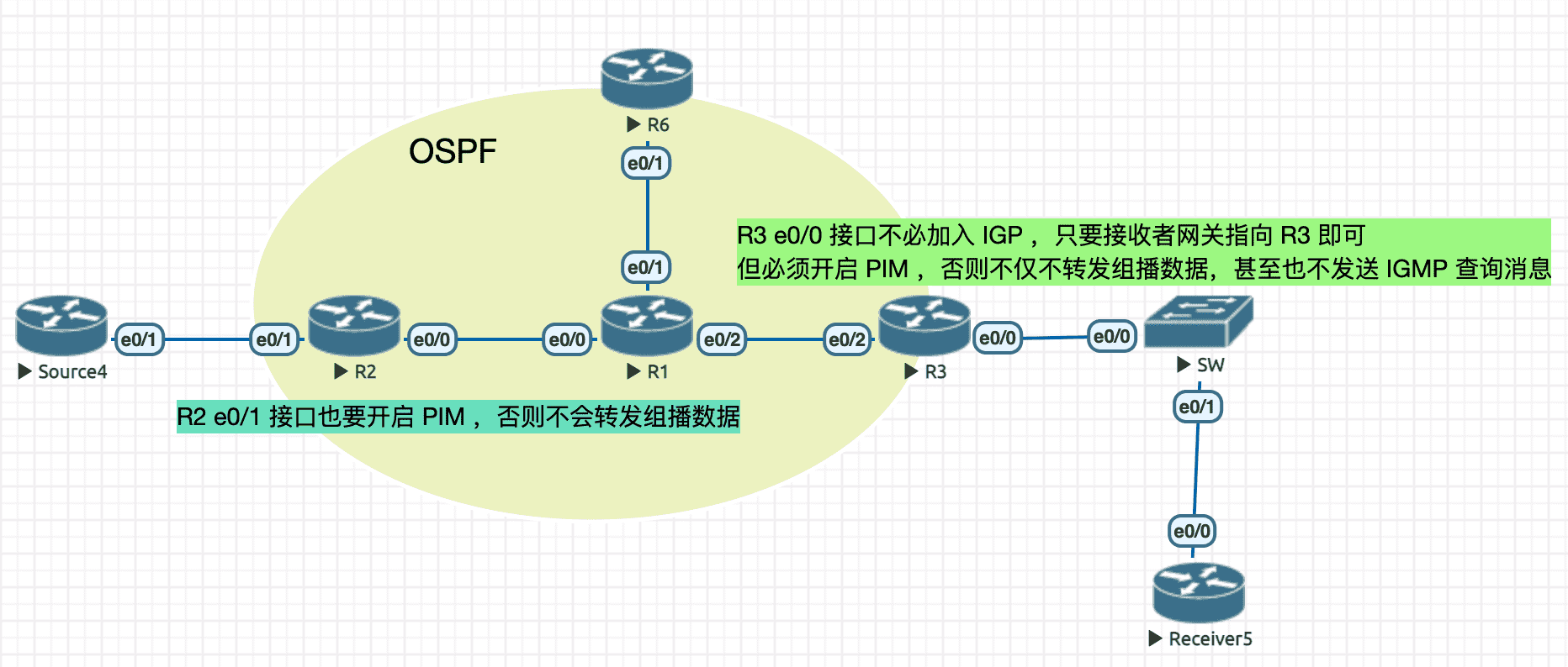
Figure 10: 实验拓扑
实验配置
----------------- Source4 ----------------------
!! 并没有开启 multicast-routing ,也没有在接口上启用 PIM
!! Source4 只是个普通的路由器
en
conf t
hostname Source4
no ip do lo
line con 0
  exec-timeout 0 0
  logging synchronous
int e0/1
  ip address 10.1.24.4 255.255.255.0
  no sh
----------------- R2 ----------------------
en
conf t
hostname R2
no ip do lo
line con 0
  exec-timeout 0 0
  logging synchronous
ip multicast-routing ! enable multicast
int lo0
  ip address 2.2.2.2 255.255.255.255
int e0/0
  ip address 10.1.12.2 255.255.255.0
  ip pim dense-mode ! have to specify mode when using multicast
  no sh
int e0/1
  ip address 10.1.24.2 255.255.255.0
  ip pim dense-mode ! have to specify mode when using multicast
  no sh
router ospf 110
  router-id 2.2.2.2
  network 10.1.24.2 0.0.0.0 area 0
  network 10.1.12.2 0.0.0.0 area 0
----------------- R1 ----------------------
en
conf t
hostname R1
no ip do lo
line con 0
  exec-timeout 0 0
  logging synchronous
exit
ip multicast-routing ! enable multicast
int lo0
  ip address 1.1.1.1 255.255.255.255
int e0/0
  ip address 10.1.12.1 255.255.255.0
  ip pim dense-mode ! have to specify mode when using multicast
  no sh
int e0/1
  ip address 10.1.16.1 255.255.255.0
  ip pim dense-mode ! have to specify mode when using multicast
  no sh
int e0/2
  ip address 10.1.13.1 255.255.255.0
  ip pim dense-mode ! have to specify mode when using multicast
  no sh
router ospf 110
  router-id 1.1.1.1
  network 10.1.12.1 0.0.0.0 area 0
  network 10.1.13.1 0.0.0.0 area 0
  network 10.1.16.1 0.0.0.0 area 0
----------------- R6 ----------------------
en
conf t
hostname R6
no ip do lo
line con 0
  exec-timeout 0 0
  logging synchronous
ip multicast-routing ! enable multicast
int lo0
  ip address 6.6.6.6 255.255.255.255
int e0/1
  ip address 10.1.16.6 255.255.255.0
  ip pim dense-mode ! have to specify mode when using multicast
  no sh
router ospf 110
  router-id 6.6.6.6
  network 10.1.16.6 0.0.0.0 area 0
----------------- R3 ----------------------
en
conf t
hostname R3
no ip do lo
line con 0
  exec-timeout 0 0
  logging synchronous
ip multicast-routing ! enable multicast
int lo0
  ip address 3.3.3.3 255.255.255.255
int e0/0
  ip address 10.1.35.3 255.255.255.0
  ip pim dense-mode ! have to specify mode when using multicast
  no sh
int e0/2
  ip address 10.1.13.3 255.255.255.0
  ip pim dense-mode ! have to specify mode when using multicast
  no sh
router ospf 110
  router-id 3.3.3.3
  network 10.1.13.3 0.0.0.0 area 0
  !! no need to network 10.1.35.0/24
----------------- Receiver5 ----------------------
en
conf t
hostname Receiver5
no ip do lo
line con 0
  exec-timeout 0 0
  logging synchronous
no ip routing
ip default-gateway 10.1.35.3
int e0/0
  ip address 10.1.35.5 255.255.255.0
  ip igmp join-group 239.1.1.1
  no sh
查看 PIM 信息
R1#sh ip pim neighbor
PIM Neighbor Table
Mode: B - Bidir Capable, DR - Designated Router, N - Default DR Priority,
      P - Proxy Capable, S - State Refresh Capable, G - GenID Capable,
      L - DR Load-balancing Capable
Neighbor          Interface                Uptime/Expires    Ver   DR
Address                                                            Prio/Mode
10.1.12.2         Ethernet0/0              00:04:35/00:01:34 v2    1 / DR S P G
10.1.16.6         Ethernet0/1              00:00:19/00:01:25 v2    1 / DR S P G
10.1.13.3         Ethernet0/2              00:04:11/00:01:29 v2    1 / DR S P G
R1#sh ip pim interface

Address          Interface                Ver/   Nbr    Query  DR         DR
                                          Mode   Count  Intvl  Prior
10.1.12.1        Ethernet0/0              v2/D   1      30     1          10.1.12.2
10.1.16.1        Ethernet0/1              v2/D   1      30     1          10.1.16.6
10.1.13.1        Ethernet0/2              v2/D   1      30     1          10.1.13.3
R1#
查看 R2 组播路由
R2#sh ip mroute
IP Multicast Routing Table
Flags: D - Dense, S - Sparse, B - Bidir Group, s - SSM Group, C - Connected,
       L - Local, P - Pruned, R - RP-bit set, F - Register flag,
       T - SPT-bit set, J - Join SPT, M - MSDP created entry, E - Extranet,
       X - Proxy Join Timer Running, A - Candidate for MSDP Advertisement,
       U - URD, I - Received Source Specific Host Report,
       Z - Multicast Tunnel, z - MDT-data group sender,
       Y - Joined MDT-data group, y - Sending to MDT-data group,
       G - Received BGP C-Mroute, g - Sent BGP C-Mroute,
       N - Received BGP Shared-Tree Prune, n - BGP C-Mroute suppressed,
       Q - Received BGP S-A Route, q - Sent BGP S-A Route,
       V - RD & Vector, v - Vector, p - PIM Joins on route,
       x - VxLAN group
Outgoing interface flags: H - Hardware switched, A - Assert winner, p - PIM Join
 Timers: Uptime/Expires
 Interface state: Interface, Next-Hop or VCD, State/Mode

(*, 239.1.1.1), 00:13:08/stopped, RP 0.0.0.0, flags: D ! 任何情况下,如果产生一个 (S,G) 表项,也会同时产生 (*,G) 表项,在 dense-mode 中不关心此表项
  Incoming interface: Null, RPF nbr 0.0.0.0
  Outgoing interface list:
    Ethernet0/0, Forward/Dense, 00:13:08/stopped

(10.1.24.4, 239.1.1.1), 00:13:08/00:01:38, flags: T  ! dense-mode 只关注此表项
  Incoming interface: Ethernet0/1, RPF nbr 0.0.0.0
  Outgoing interface list:
    Ethernet0/0, Forward/Dense, 00:13:08/stopped

(*, 224.0.1.40), 00:34:58/00:02:54, RP 0.0.0.0, flags: DCL
  Incoming interface: Null, RPF nbr 0.0.0.0
  Outgoing interface list:
    Ethernet0/0, Forward/Dense, 00:34:58/stopped
查看 R1 组播路由
R1#sh ip mroute
IP Multicast Routing Table
Flags: D - Dense, S - Sparse, B - Bidir Group, s - SSM Group, C - Connected,
       L - Local, P - Pruned, R - RP-bit set, F - Register flag,
       T - SPT-bit set, J - Join SPT, M - MSDP created entry, E - Extranet,
       X - Proxy Join Timer Running, A - Candidate for MSDP Advertisement,
       U - URD, I - Received Source Specific Host Report,
       Z - Multicast Tunnel, z - MDT-data group sender,
       Y - Joined MDT-data group, y - Sending to MDT-data group,
       G - Received BGP C-Mroute, g - Sent BGP C-Mroute,
       N - Received BGP Shared-Tree Prune, n - BGP C-Mroute suppressed,
       Q - Received BGP S-A Route, q - Sent BGP S-A Route,
       V - RD & Vector, v - Vector, p - PIM Joins on route,
       x - VxLAN group
Outgoing interface flags: H - Hardware switched, A - Assert winner, p - PIM Join
 Timers: Uptime/Expires
 Interface state: Interface, Next-Hop or VCD, State/Mode

(*, 239.1.1.1), 00:04:32/stopped, RP 0.0.0.0, flags: D
  Incoming interface: Null, RPF nbr 0.0.0.0
  Outgoing interface list:
    Ethernet0/2, Forward/Dense, 00:04:32/stopped
    Ethernet0/1, Forward/Dense, 00:04:32/stopped
    Ethernet0/0, Forward/Dense, 00:04:32/stopped

(10.1.24.4, 239.1.1.1), 00:01:22/00:01:37, flags: T
  Incoming interface: Ethernet0/0, RPF nbr 10.1.12.2
  Outgoing interface list:
    Ethernet0/1, Prune/Dense, 00:01:12/00:01:47 ! 还剩多少时间需要再次泛洪组播数据,前后两个时间加起来是 3 分钟
    Ethernet0/2, Forward/Dense, 00:07:10/stopped ! 收到 Prune 消息才会重新倒计时,当接口处于 Forward 状态,超时时间就会显示 stopped

(*, 224.0.1.40), 00:04:33/00:02:56, RP 0.0.0.0, flags: DCL
  Incoming interface: Null, RPF nbr 0.0.0.0
  Outgoing interface list:
    Ethernet0/2, Forward/Dense, 00:04:33/stopped
    Ethernet0/1, Forward/Dense, 00:04:33/stopped
    Ethernet0/0, Forward/Dense, 00:04:33/stopped
6 Sparse-Mode
6.1 原理
- SM 模型假设网络中的组成员分布是分散的,当网段出现组成员时,才构建组播路由,因此比 DM 模式更节省资源
- 选择某一个 PIM 路由器作为公用根节点,即 RP ,组播数据 最初 通过 RP 沿共享树向接收者转发
- 当组成员加入时(igmp join),接收者的首跳路由器会向 RP 发送 组加入消息 ,该消息经过一个个路由器最后到达 RP ,所经过的路径就形成了以 RP 为根的共享树(RPT)
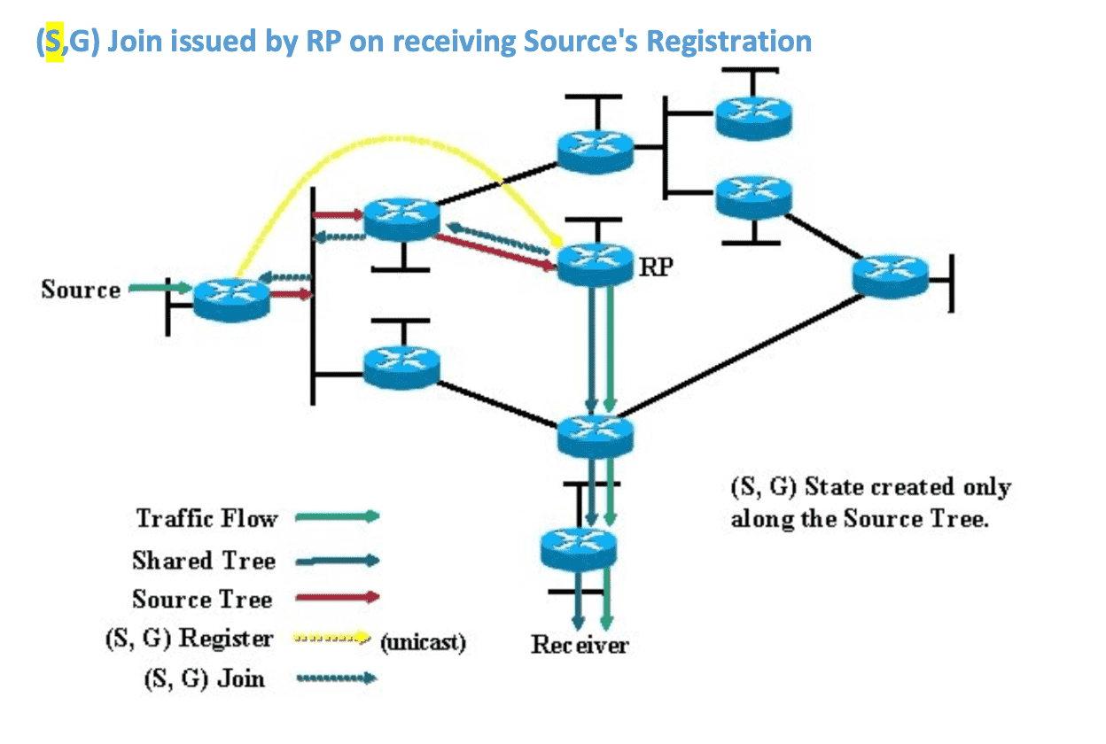
- 发送端发送组播数据时,先由第一跳路由器向 RP 进行 单播注册 ,Register 消息到达 RP 后触发 源树 的建立(RP 使用 Join 消息 反向 寻找组播源)。 同时,组播数据会作为 Register 消息的 payload 沿着之前建立的 RPT 传给接收者
- 当组播数据到达接收方的首跳路由器,会触发 共享树到源树的切换 ,即找到最合理的路径,直接在源与接收方之间发送组播数据(没必要每次都经过 RP)
接收者向 RP 发起 (*,G) Join
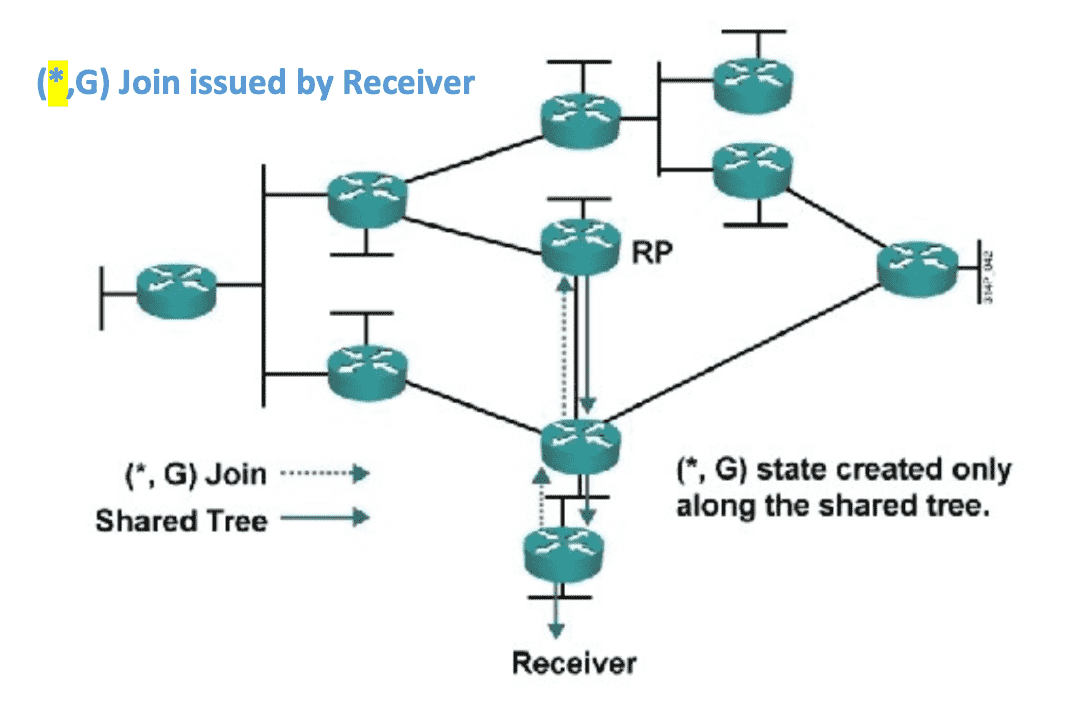
源向RP Register ,RP 向源(S,G) Join
注册的作用在于通知 RP 检查是否存在组播接收者,如果有接收者后续的操作才有意义。
RP 向组播源发起 Join 后,源与 RP 之间就建立了最短路径树(SPT)。
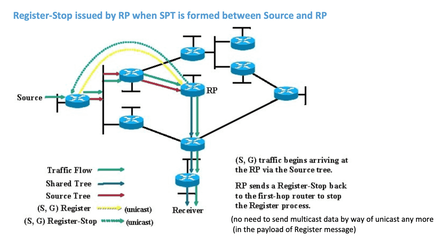
RP 向源 Register Stop
RP 通知组播源不要再把组播数据借由 Register 消息发送过来了:
- 如果存在接收者,RP 肯定已经向源发起过 Join ,源树以建立,后续组播数据可以基于组播路由表进行传递
- 如果没有接收者,由于 RP 不会发送 Join ,源树不会建立,也不会形成组播路由表,组播数据也就无法传递
最后一跳路由器执行源树切换
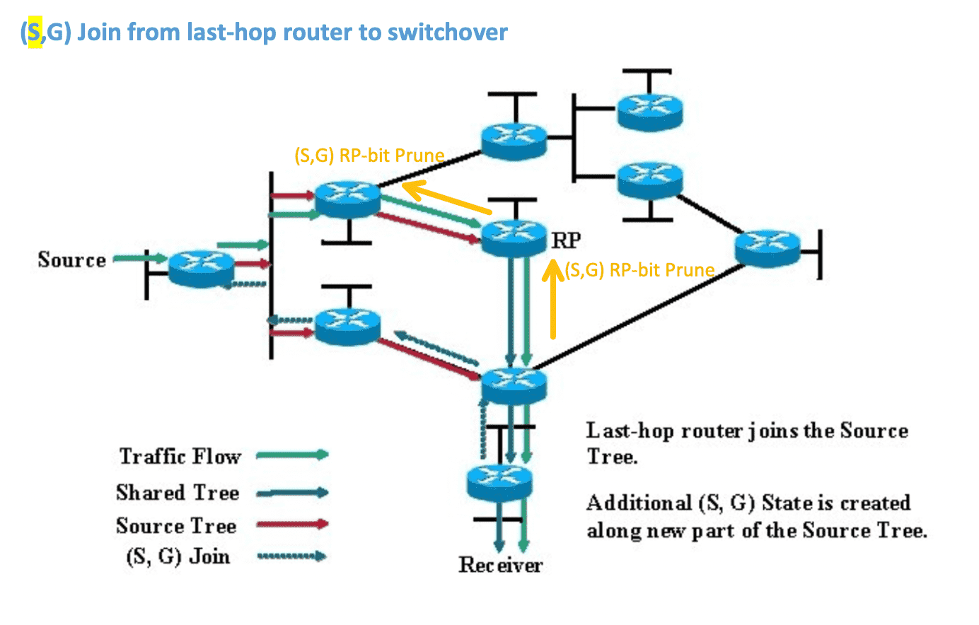
6.2 配置示例(静态RP) 2
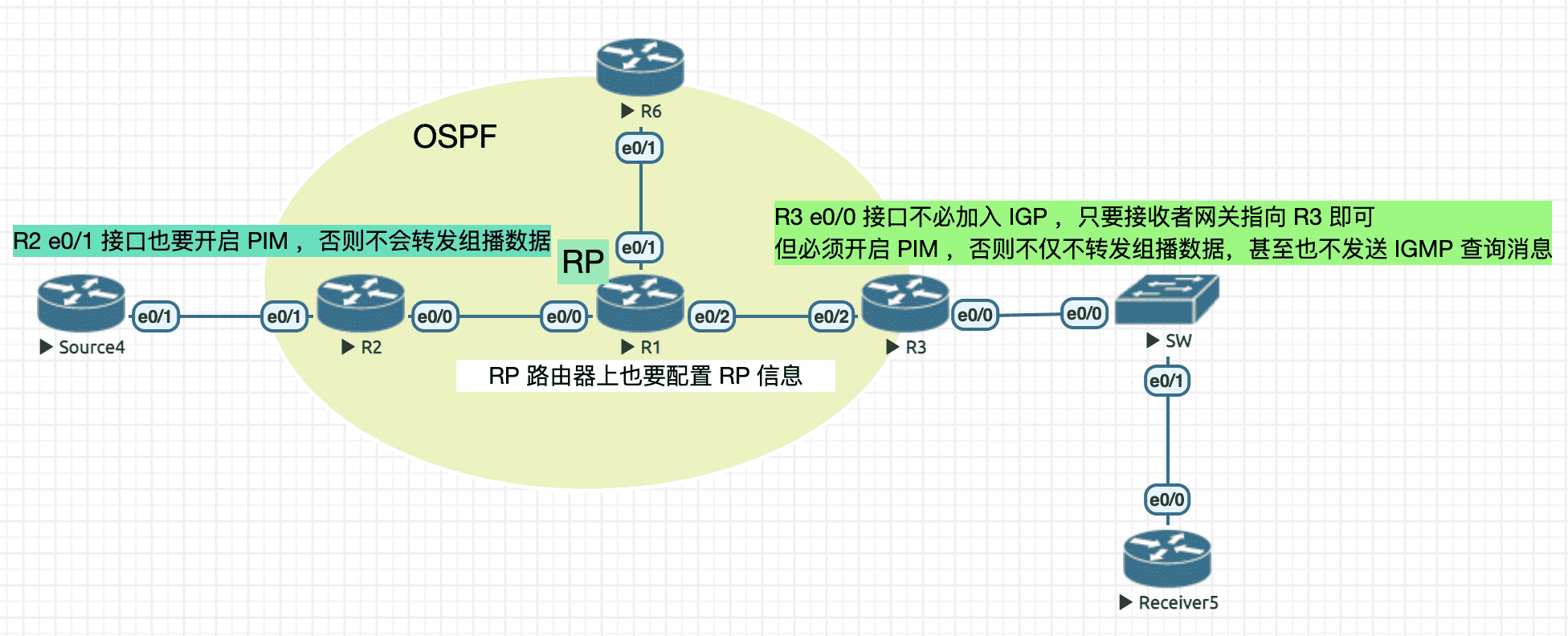
Figure 15: 实验环境
实验配置
----------------- Source4 ----------------------
!! 并没有开启 multicast-routing ,也没有在接口上启用 PIM
!! Source4 就是个普通的路由器
en
conf t
hostname Source4
no ip do lo
line con 0
  exec-timeout 0 0
  logging synchronous
int e0/1
  ip address 10.1.24.4 255.255.255.0
  no sh
----------------- R2 ----------------------
en
conf t
hostname R2
no ip do lo
line con 0
  exec-timeout 0 0
  logging synchronous
ip multicast-routing ! enable multicast
ip pim rp-address 1.1.1.1 ! every PIM router will do this (include RP itself)
int lo0
  ip address 2.2.2.2 255.255.255.255
int e0/0
  ip address 10.1.12.2 255.255.255.0
  ip pim sparse-mode ! have to specify mode when using multicast
  no sh
int e0/1
  ip address 10.1.24.2 255.255.255.0
  ip pim sparse-mode ! have to specify mode when using multicast
  no sh
router ospf 110
  router-id 2.2.2.2
  network 10.1.24.2 0.0.0.0 area 0
  network 10.1.12.2 0.0.0.0 area 0
----------------- R1 ----------------------
en
conf t
hostname R1
no ip do lo
line con 0
  exec-timeout 0 0
  logging synchronous
ip multicast-routing ! enable multicast
ip pim rp-address 1.1.1.1 ! every PIM router will do this (include RP itself)
int lo0
  ip address 1.1.1.1 255.255.255.255
int e0/0
  ip address 10.1.12.1 255.255.255.0
  ip pim sparse-mode ! have to specify mode when using multicast
  no sh
int e0/1
  ip address 10.1.16.1 255.255.255.0
  ip pim sparse-mode ! have to specify mode when using multicast
  no sh
int e0/2
  ip address 10.1.13.1 255.255.255.0
  ip pim sparse-mode ! have to specify mode when using multicast
  no sh
router ospf 110
  router-id 1.1.1.1
  network 1.1.1.1   0.0.0.0 area 0 ! use lo0 as RP address and network it
  network 10.1.12.1 0.0.0.0 area 0
  network 10.1.13.1 0.0.0.0 area 0
  network 10.1.16.1 0.0.0.0 area 0
----------------- R6 ----------------------
en
conf t
hostname R6
no ip do lo
line con 0
  exec-timeout 0 0
  logging synchronous
ip multicast-routing ! enable multicast
ip pim rp-address 1.1.1.1 ! every PIM router will do this (include RP itself)
int lo0
  ip address 6.6.6.6 255.255.255.255
int e0/1
  ip address 10.1.16.6 255.255.255.0
  ip pim sparse-mode ! have to specify mode when using multicast
  no sh
router ospf 110
  router-id 6.6.6.6
  network 10.1.16.6 0.0.0.0 area 0
----------------- R3 ----------------------
en
conf t
hostname R3
no ip do lo
line con 0
  exec-timeout 0 0
  logging synchronous
ip multicast-routing ! enable multicast
ip pim rp-address 1.1.1.1 ! every PIM router will do this (include RP itself)
int lo0
  ip address 3.3.3.3 255.255.255.255
int e0/0
  ip address 10.1.35.3 255.255.255.0
  ip pim sparse-mode ! have to specify mode when using multicast
  no sh
int e0/2
  ip address 10.1.13.3 255.255.255.0
  ip pim sparse-mode ! have to specify mode when using multicast
  no sh
router ospf 110
  router-id 3.3.3.3
  network 10.1.13.3 0.0.0.0 area 0
  !! no need to network 10.1.35.0/24
----------------- Receiver5 ----------------------
en
conf t
hostname Receiver5
no ip do lo
line con 0
  exec-timeout 0 0
  logging synchronous
no ip routing
ip default-gateway 10.1.35.3
int e0/0
  ip address 10.1.35.5 255.255.255.0
  ip igmp join-group 239.1.1.1
  no sh
查看隧道接口
R1#sh ip interface brief
Interface                  IP-Address      OK? Method Status                Protocol
Ethernet0/0                10.1.12.1       YES manual up                    up
Ethernet0/1                10.1.16.1       YES manual up                    up
Ethernet0/2                10.1.13.1       YES manual up                    up
Ethernet0/3                unassigned      YES unset  administratively down down
Loopback0                  1.1.1.1         YES manual up                    up
Tunnel0                    10.1.12.1       YES unset  up                    up
Tunnel1                    1.1.1.1         YES unset  up                    up
R1#conf t
Enter configuration commands, one per line.  End with CNTL/Z.
R1(config)#int tun0
%Tunnel0 used by PIM for Registering, configuration not allowed
R1(config)#int tun1
%Tunnel1 used by PIM for Registering, configuration not allowed
查看 RP 组播路由表
R1#sh ip mroute
IP Multicast Routing Table
Flags: D - Dense, S - Sparse, B - Bidir Group, s - SSM Group, C - Connected,
       L - Local, P - Pruned, R - RP-bit set, F - Register flag,
       T - SPT-bit set, J - Join SPT, M - MSDP created entry, E - Extranet,
       X - Proxy Join Timer Running, A - Candidate for MSDP Advertisement,
       U - URD, I - Received Source Specific Host Report,
       Z - Multicast Tunnel, z - MDT-data group sender,
       Y - Joined MDT-data group, y - Sending to MDT-data group,
       G - Received BGP C-Mroute, g - Sent BGP C-Mroute,
       N - Received BGP Shared-Tree Prune, n - BGP C-Mroute suppressed,
       Q - Received BGP S-A Route, q - Sent BGP S-A Route,
       V - RD & Vector, v - Vector, p - PIM Joins on route,
       x - VxLAN group
Outgoing interface flags: H - Hardware switched, A - Assert winner, p - PIM Join
 Timers: Uptime/Expires
 Interface state: Interface, Next-Hop or VCD, State/Mode

(*, 239.1.1.1), 00:10:35/00:02:46, RP 1.1.1.1, flags: S
  Incoming interface: Null, RPF nbr 0.0.0.0
  Outgoing interface list:
    Ethernet0/2, Forward/Sparse, 00:10:35/00:02:46

(10.1.24.4, 239.1.1.1), 00:09:42/00:01:51, flags: T ! 与组播源之间形成源树
  Incoming interface: Ethernet0/0, RPF nbr 10.1.12.2
  Outgoing interface list:
    Ethernet0/2, Forward/Sparse, 00:09:42/00:02:46

(*, 224.0.1.40), 00:12:16/00:03:19, RP 1.1.1.1, flags: SJCL
  Incoming interface: Null, RPF nbr 0.0.0.0
  Outgoing interface list:
    Ethernet0/1, Forward/Sparse, 00:10:09/00:03:12
    Ethernet0/2, Forward/Sparse, 00:11:20/00:02:40
    Ethernet0/0, Forward/Sparse, 00:12:14/00:03:19
查看接收端首跳路由器组播路由表
R3#sh ip mroute
IP Multicast Routing Table
Flags: D - Dense, S - Sparse, B - Bidir Group, s - SSM Group, C - Connected,
       L - Local, P - Pruned, R - RP-bit set, F - Register flag,
       T - SPT-bit set, J - Join SPT, M - MSDP created entry, E - Extranet,
       X - Proxy Join Timer Running, A - Candidate for MSDP Advertisement,
       U - URD, I - Received Source Specific Host Report,
       Z - Multicast Tunnel, z - MDT-data group sender,
       Y - Joined MDT-data group, y - Sending to MDT-data group,
       G - Received BGP C-Mroute, g - Sent BGP C-Mroute,
       N - Received BGP Shared-Tree Prune, n - BGP C-Mroute suppressed,
       Q - Received BGP S-A Route, q - Sent BGP S-A Route,
       V - RD & Vector, v - Vector, p - PIM Joins on route,
       x - VxLAN group
Outgoing interface flags: H - Hardware switched, A - Assert winner, p - PIM Join
 Timers: Uptime/Expires
 Interface state: Interface, Next-Hop or VCD, State/Mode

(*, 239.1.1.1), 00:10:12/stopped, RP 1.1.1.1, flags: SJC
  Incoming interface: Ethernet0/2, RPF nbr 10.1.13.1
  Outgoing interface list:
    Ethernet0/0, Forward/Sparse, 00:10:12/00:02:52

(10.1.24.4, 239.1.1.1), 00:09:19/00:01:33, flags: JT ! 通过 Join 消息与组播源之间形成源树,完成 SPT 切换
  Incoming interface: Ethernet0/2, RPF nbr 10.1.13.1
  Outgoing interface list:
    Ethernet0/0, Forward/Sparse, 00:09:19/00:02:52

(*, 224.0.1.40), 00:11:15/00:02:51, RP 1.1.1.1, flags: SJCL
  Incoming interface: Ethernet0/2, RPF nbr 10.1.13.1
  Outgoing interface list:
    Ethernet0/0, Forward/Sparse, 00:11:13/00:02:51
6.3 DR 3 , 4
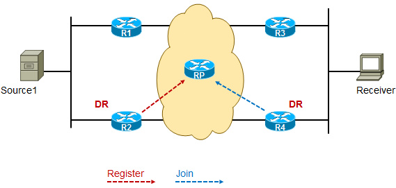
Figure 16: DR 在源侧和接收侧
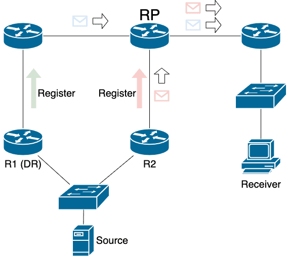
DR 在 sparse-mode 中的作用主要是 负责发送 Join/Register 消息 :
靠近接收者的 DR 负责向 RP 发送 Join 消息从而形成共享树(同时负责将来自源的组播数据转发给接收者)
如果没有 DR 机制
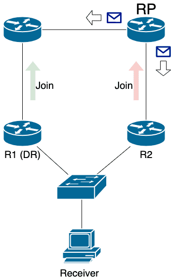
如下图所示,如果 R1, R2 同时向 RP 发送 Join ,RP 上针对同一组会有两个出接口,Receiver 会收到 重复的 组播数据报文。
靠近源的 DR 负责将源的组播数据发给 RP (以及发送 Register 消息)
如果没有 DR 机制
如下图所示,如果 R1, R2 同时向 RP 进行注册 ,Receiver 亦会收到 重复的 组播数据报文。
6.4 RP
RP ,汇聚点,即组播源和接收者 约会见面的地方 ,用于 sparse 模式中:
- 组播源通过首跳路由器与 RP 注册(Register)
- 组播接收者通过 local DR 加入 (join) 以 RP 为根的共享树
RP 的意义在于通过掌握接收者的信息,将 首个 组播数据 以最有效率的方式 发送到接收者,接收者收到数据完成源树切换,这样源与接收者之间就以最快速度建立了源树(SPT)。
即共享树的根,有三种指定方式:
6.4.1 手动指定
参考 6.2
6.4.2 Auto RP
该解决方案需要用到两个角色,即映射代理 (MA) 和候选 RP (C-RP) 。
所有的 C-RP 把候选信息发向组播地址 224.0.1.39 (Cisco-Announce) ,只有 MA 才会侦听该组播地址并优选 IP 地址大的 C-RP 作为 RP ,并通过组播地址 224.0.1.40 5 (Cisco-Discovery) 通告给所有组播设备。
每个组会映射到一个 C-RP 作为 RP ,每个 C-RP 可以是属于不同的组的 RP ,这样达到了 RP 负载均衡的作用。
由于 AutoRP 消息(Announce/Discovery) 具有 泛洪 的性质,组播数据(224.0.1.39/224.0.1.40)需要工作在 dense-mode 下,实际中通常会将 PIM 接口模式设置为 sparse-dense-mode 。
如果 PIM 接口使用的是 sparse-mode ,需要在所有 PIM 路由器上配置 ip pim autorp listener ,这样才能使 AutoRP 消息在 sparse-mode 接口下得以泛洪。
6.4.2.1 配置示例
实验配置
----------------- Source4 ----------------------
en
conf t
hostname Source4
no ip do lo
line con 0
  exec-timeout 0 0
  logging synchronous
int e0/1
  ip address 10.1.24.4 255.255.255.0
  no sh
----------------- R2 (MA) ----------------------
en
conf t
hostname R2
no ip do lo
line con 0
  exec-timeout 0 0
  logging synchronous
ip multicast-routing ! enable multicast
int lo0
  ip address 2.2.2.2 255.255.255.255
  ip pim sparse-dense-mode ! will send multicast data (224.0.1.40) through this ifc, so have to specify mode
ip pim send-rp-discovery Loopback0 scope 255 ! MA needs this config
int e0/0
  ip address 10.1.12.2 255.255.255.0
  ip pim sparse-mode ! have to specify mode when using multicast
  no sh
int e0/1
  ip address 10.1.24.2 255.255.255.0
  ip pim sparse-dense-mode ! have to specify mode when using multicast
  no sh
router ospf 110
  router-id 2.2.2.2
  network 10.1.24.2 0.0.0.0 area 0
  network 10.1.12.2 0.0.0.0 area 0
  network 2.2.2.2 0.0.0.0 area 0 ! must network MA's IP
----------------- R1 (C-RP) ----------------------
en
conf t
hostname R1
no ip do lo
line con 0
  exec-timeout 0 0
  logging synchronous
ip multicast-routing ! enable multicast
int lo0
  ip address 1.1.1.1 255.255.255.255
  ip pim sparse-dense-mode ! will send multicast data (224.0.1.39) through this ifc, so have to specify mode
ip pim send-rp-announce Loopback0 scope 255 ! C-RP needs this config
int e0/0
  ip address 10.1.12.1 255.255.255.0
  ip pim sparse-dense-mode ! have to specify mode when using multicast
  no sh
int e0/1
  ip address 10.1.16.1 255.255.255.0
  ip pim sparse-dense-mode ! have to specify mode when using multicast
  no sh
int e0/2
  ip address 10.1.13.1 255.255.255.0
  ip pim sparse-dense-mode ! have to specify mode when using multicast
  no sh
router ospf 110
  router-id 1.1.1.1
  network 1.1.1.1   0.0.0.0 area 0 ! use lo0 as RP address and network it
  network 10.1.12.1 0.0.0.0 area 0
  network 10.1.13.1 0.0.0.0 area 0
  network 10.1.16.1 0.0.0.0 area 0
----------------- R6 ----------------------
en
conf t
hostname R6
no ip do lo
line con 0
  exec-timeout 0 0
  logging synchronous
ip multicast-routing ! enable multicast
int lo0
  ip address 6.6.6.6 255.255.255.255
int e0/1
  ip address 10.1.16.6 255.255.255.0
  ip pim sparse-dense-mode ! have to specify mode when using multicast
  no sh
router ospf 110
  router-id 6.6.6.6
  network 10.1.16.6 0.0.0.0 area 0
----------------- R3 ----------------------
en
conf t
hostname R3
no ip do lo
line con 0
  exec-timeout 0 0
  logging synchronous
ip multicast-routing ! enable multicast
int lo0
  ip address 3.3.3.3 255.255.255.255
int e0/0
  ip address 10.1.35.3 255.255.255.0
  ip pim sparse-dense-mode ! have to specify mode when using multicast
  no sh
int e0/2
  ip address 10.1.13.3 255.255.255.0
  ip pim sparse-dense-mode ! have to specify mode when using multicast
  no sh
router ospf 110
  router-id 3.3.3.3
  network 10.1.13.3 0.0.0.0 area 0
  !! no need to network 10.1.35.0/24
----------------- Receiver5 ----------------------
en
conf t
hostname Receiver5
no ip do lo
line con 0
  exec-timeout 0 0
  logging synchronous
no ip routing
ip default-gateway 10.1.35.3
int e0/0
  ip address 10.1.35.5 255.255.255.0
  ip igmp join-group 239.1.1.1
  no sh
查看 R2(MA) 信息
R2#sh ip pim rp
Group: 239.1.1.1, RP: 1.1.1.1, uptime 00:09:22, expires 00:02:34 ! 组 239.1.1.1 对应的 RP 是 1.1.1.1
R2#sh ip pim rp mapping
PIM Group-to-RP Mappings
This system is an RP-mapping agent (Loopback0) ! 表明本路由器是 MA

Group(s) 224.0.0.0/4
  RP 1.1.1.1 (?), v2v1
    Info source: 1.1.1.1 (?), elected via Auto-RP
         Uptime: 00:09:24, expires: 00:02:33
查看 R6 信息
R6#sh ip mroute
IP Multicast Routing Table
Flags: D - Dense, S - Sparse, B - Bidir Group, s - SSM Group, C - Connected,
       L - Local, P - Pruned, R - RP-bit set, F - Register flag,
       T - SPT-bit set, J - Join SPT, M - MSDP created entry, E - Extranet,
       X - Proxy Join Timer Running, A - Candidate for MSDP Advertisement,
       U - URD, I - Received Source Specific Host Report,
       Z - Multicast Tunnel, z - MDT-data group sender,
       Y - Joined MDT-data group, y - Sending to MDT-data group,
       G - Received BGP C-Mroute, g - Sent BGP C-Mroute,
       N - Received BGP Shared-Tree Prune, n - BGP C-Mroute suppressed,
       Q - Received BGP S-A Route, q - Sent BGP S-A Route,
       V - RD & Vector, v - Vector, p - PIM Joins on route,
       x - VxLAN group
Outgoing interface flags: H - Hardware switched, A - Assert winner, p - PIM Join
 Timers: Uptime/Expires
 Interface state: Interface, Next-Hop or VCD, State/Mode

(*, 224.0.1.39), 00:10:23/stopped, RP 0.0.0.0, flags: D
  Incoming interface: Null, RPF nbr 0.0.0.0
  Outgoing interface list:
    Ethernet0/1, Forward/Sparse-Dense, 00:10:23/stopped

(1.1.1.1, 224.0.1.39), 00:10:23/00:02:26, flags: PT ! 其实收到了 C-RP 的 Annouce 消息
  Incoming interface: Ethernet0/1, RPF nbr 10.1.16.1
  Outgoing interface list: Null

(*, 224.0.1.40), 00:11:13/stopped, RP 0.0.0.0, flags: DCL
  Incoming interface: Null, RPF nbr 0.0.0.0
  Outgoing interface list:
    Ethernet0/1, Forward/Sparse-Dense, 00:11:13/stopped

(2.2.2.2, 224.0.1.40), 00:10:24/00:02:26, flags: PLTX  ! 其实收到了 MA 的 Discovery 消息
  Incoming interface: Ethernet0/1, RPF nbr 10.1.16.1
  Outgoing interface list: Null
R6#sh ip pim rp ! 但查不到任何关于 RP 的信息,猜测是因为 R6 的路径上不存在接收者,保存 RP 信息实际上并没有意义(即使已经从 MA 收到了 Discovery 消息)
6.4.2.2 RP announcement filter
因为使用了组播地址相互传递数据,为了防止 RP 信息相互影响, 需要 在域间路由器互联接口上 使用以下方法来设置传递边界:
access-list AclNumber deny 224.0.1.39 ! 阻止 Annouce 消息传递
access-list AclNumber deny 224.0.1.40 ! 阻止 Discovery 消息传递
access-list AclNumber permit any
!
interface Ethernet0/0
 ip multicast boundary AclNumber
6.4.3 BSR (公有标准)
需要用到两个角色,即 BSR [从多个候选 BSR (C-BSR) 中选举出来] 和候选 RP (C-RP)。
PIM-SM 网络启动后,BSR 负责收集网络内的 候选 RP 发来的 Advertisement 信息, 然后为每个组播组选择 部分 C-RP 信息组成 RP-Set (即 Group-RP Mapping Database), 并发布到整个网络中的 PIM 路由器,这样所有路由器都会知道 RP 的位置。
一个 PIM-SM 网络中只能有一台 选举出的 BSR ,但同时可以存在多台候选 BSR ,当 BSR 发生故障后,其余的 C-BSR 能够自动选举出新的 BSR ,从而确保业务免受中断。
6.4.3.1 BSR 选举过程
- 在网络中选择合适的路由器配置成候选 BSR (C-BSR) ,每个 C-BSR 都有优先级。当路由器配置成 C-BSR 后会启动一个定时器 (130s) 并监听网络中的 BootStrap Message 。 BootStrap Message 初始通告会发送路由器的优先级,IP 地址。
- 当 C-BSR 收到一个 Bootstrap Message 后,会把自身优先级和报文描述的优先级相比较,若对方优先级高,则不再发送只是监听 Bootstrap Message ; 若自身优先级高,则继续发送 Bootstrap Message 。
- Bootstrap Message 发送目的地址为
224.0.0.13,该报文 TTL 置为 1 ,但每个 PIM 路由器收到后都会以泛洪的方式从其他 PIM 使能接口发送出去, 这就能保证网络中所有的 PIM 路由器都能收到消息。
6.4.3.2 RP 选举过程
- 当 C-RP 收到 BM (Bootstrap Message) 后,可以从该报文中获悉谁是 BSR ,然后 C-RP 周期性(60s)地通过 Candidate-RP-Advertisement Message 将自己能够服务的组以 单播 形式发给 BSR ,这样 BSR 就能收集到网络中所有 C-RP 的信息,并将这些信息整理成 RP-Set 。
- BSR 周期性(60s)地通过组播方式(
224.0.0.13)向所有 PIM 路由器发送 BM 消息(包含 RP-Set 信息),所有的路由器利用收到的 RP-Set 来确定 RP 。由于使用的选举优先级算法相同,所以选举出的 RP 也是相同的。
6.4.3.3 配置过程
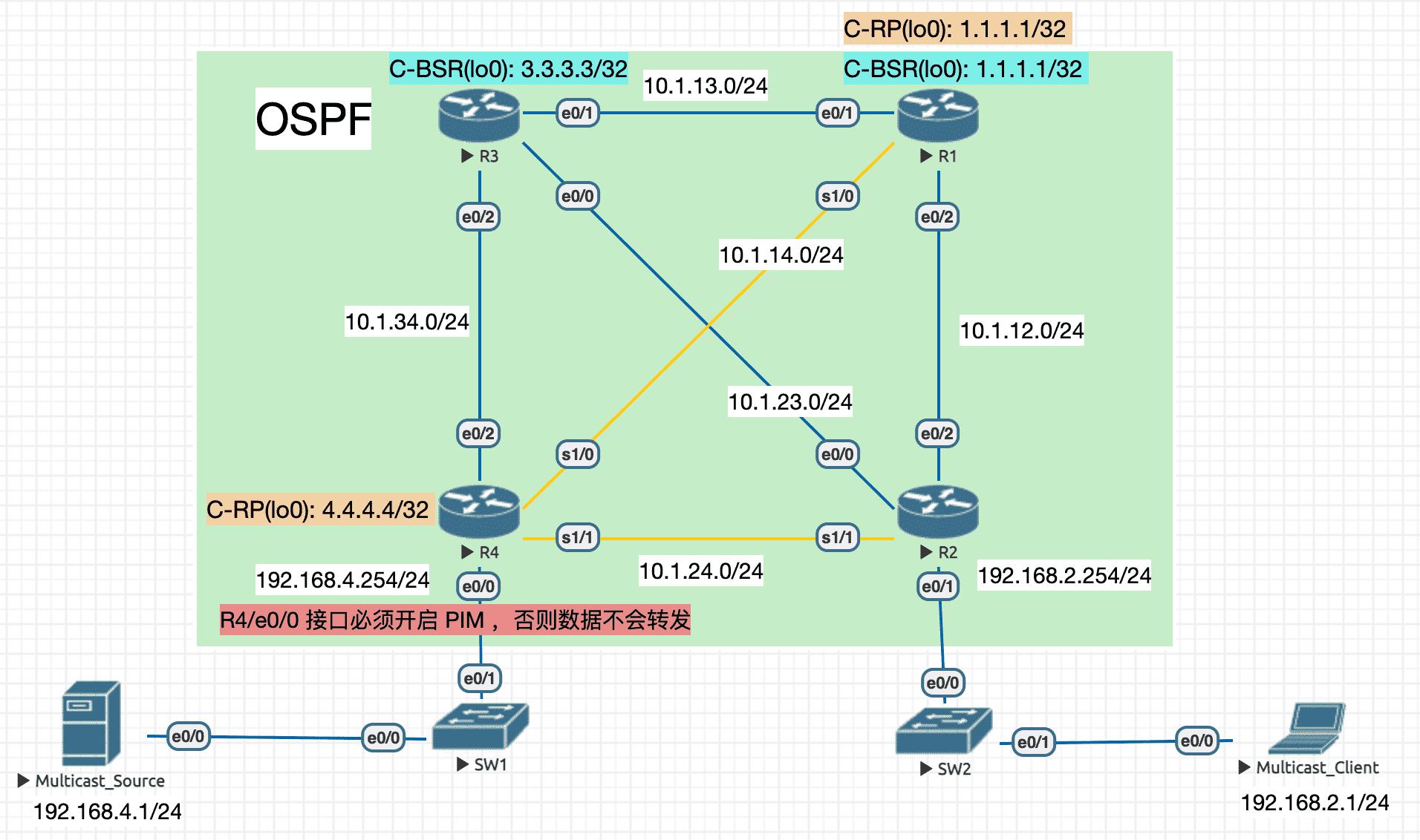
Figure 19: 实验拓扑
6.4.3.3.1 配置 C-BSR
R1 (R3 类似)
interface Loopback0
 ip address 1.1.1.1 255.255.255.255
 ip pim sparse-mode
interface Ethernet0/1
 ip address 10.1.13.1 255.255.255.0
 ip pim sparse-mode
 duplex auto
interface Ethernet0/2
 ip address 10.1.12.1 255.255.255.0
 ip pim sparse-mode
 duplex auto
interface Serial1/0
 ip address 10.1.14.1 255.255.255.0
 ip pim sparse-mode
ip pim bsr-candidate Loopback0 0 ! 可以指定优先级,值越大越优先
R2 上观察 BSR
R2#sh ip pim bsr-router
PIMv2 Bootstrap information
  BSR address: 3.3.3.3 (?)
  Uptime:      00:04:39, BSR Priority: 0, Hash mask length: 0 ! 默认的优先级和掩码都是 0
  Expires:     00:01:33
6.4.3.3.2 配置 C-RP
R1 (R4 类似)
interface Loopback0
 ip address 1.1.1.1 255.255.255.255
 ip pim sparse-mode
ip pim rp-candidate Loopback0 ! 可以指定优先级,值越小越优先
R2 上观察 RP 选举结果
R2#sh ip pim rp
Group: 239.1.1.1, RP: 4.4.4.4, uptime 00:00:06, expires 00:02:19
6.4.3.4 Multicast boundary
由于使用了泛洪的机制传递信息,为了防止 RP 信息相互影响, 需要在域间路由器互联接口使用命令 ip pim bsr-border ,该命令将使 BSR Message 不在该接口发送或接收 BM 。
6.5 改进型 mode
6.5.1 SSM (Source Specific Multicast)[非常实用]
- 是 Sparse-Mode 的变种,无所谓是否存在 RP ,如果有 RP,则相当于兼容 SM
- 不关心是否存在 RP 的原因是,既然都指定 Source 了,那直接触发生成到 Source 的最短路径树不就行了
- SSM 的组播地址范围是
232.0.0.0/8(规范,并非强制) - 只会生成
(S,G)表项
6.5.1.1 IGMPv3
可以和 v1/v2 互操作,并支持 SSM 模型。
允许接收者指定组播源,即只接收特定组播源发出的组播数据,可以说加强了接收者的控制能力。
6.5.1.2 运行条件
- 开启 sparse-mode (不需要设置 RP)
- 开启 IGMPv3
- 所有 PIM 路由器上执行
ip pim ssm range Acl或直接ip pim ssm default(Use 232.0.0.0/8 group for SSM)
6.5.2 Bi-dir PIM
该模型下只会生成 (*,G) 表项,而且没有 RPF 检查,因此只有 DF (Designated Forwarder) 接口才能 双向 转发组播数据(用于防环)。
DF 在每个网段中只有一个,可以通过 sh ip pim interface df 命令查看。DF 的选举主要是看哪个接口距离 RP 最近。
7 Anycast RP (一种 MSDP 的应用)
Anycast 最初由 RFC1546 定义,用于在 IP 网络上通过一个 IP 地址标识 一组 特定服务的主机, 同时服务访问并不关心提供服务的具体是哪一台主机。 访问该地址的数据包将被路由器提供的路由表路由到 最近 的一台主机上。因此 Anycast 指的是 找到任意的一个离本地最近的主机 。
Anycast RP 指的是在同一 AS 内设置出 多个地址完全一样的 RP (将多个物理 RP 组合成一个逻辑 RP )。当组播路由器使用 RP 时,会按照单播路由表引导到最近的 RP 上。 多个物理 RP 之间需要 借用 MSDP 共享组播源信息,这是因为组播源的第一跳路由器也会去离自己最近的 RP 进行注册,而通常和接收者共享树路径上的 RP 不是同一个。
使用 Anycast ,多个物理 RP 之间可以实现负载均衡和 备份 (不仅限于备份静态指定的 RP)。 同时也可做到 RP 的 快速切换 (这是利用 IGP 实现的,虽然动态 RP 也有一定的备份作用,但做不到快速切换,想想 BSR 方式的 holdtime 为 150s)
7.1 MSDP(组播源发现协议)
该协议是为了解决多个 PIM-SM 域间互连而开发的一种 域间组播解决方案 ,
用来发现其他 PIM-SM 域内的 组播源 信息。
MSDP 只支持在 IPv4 网络中部署,域内组播路由协议 必须是 PIM-SM 。
MSDP 在 RP 之间(可以是域内更可以是 域间)建立 MSDP 对等体 ,对等体之间交互 SA(Source-Active) 消息来共享组播源信息 并传递组播数据 。
7.2 配置实验
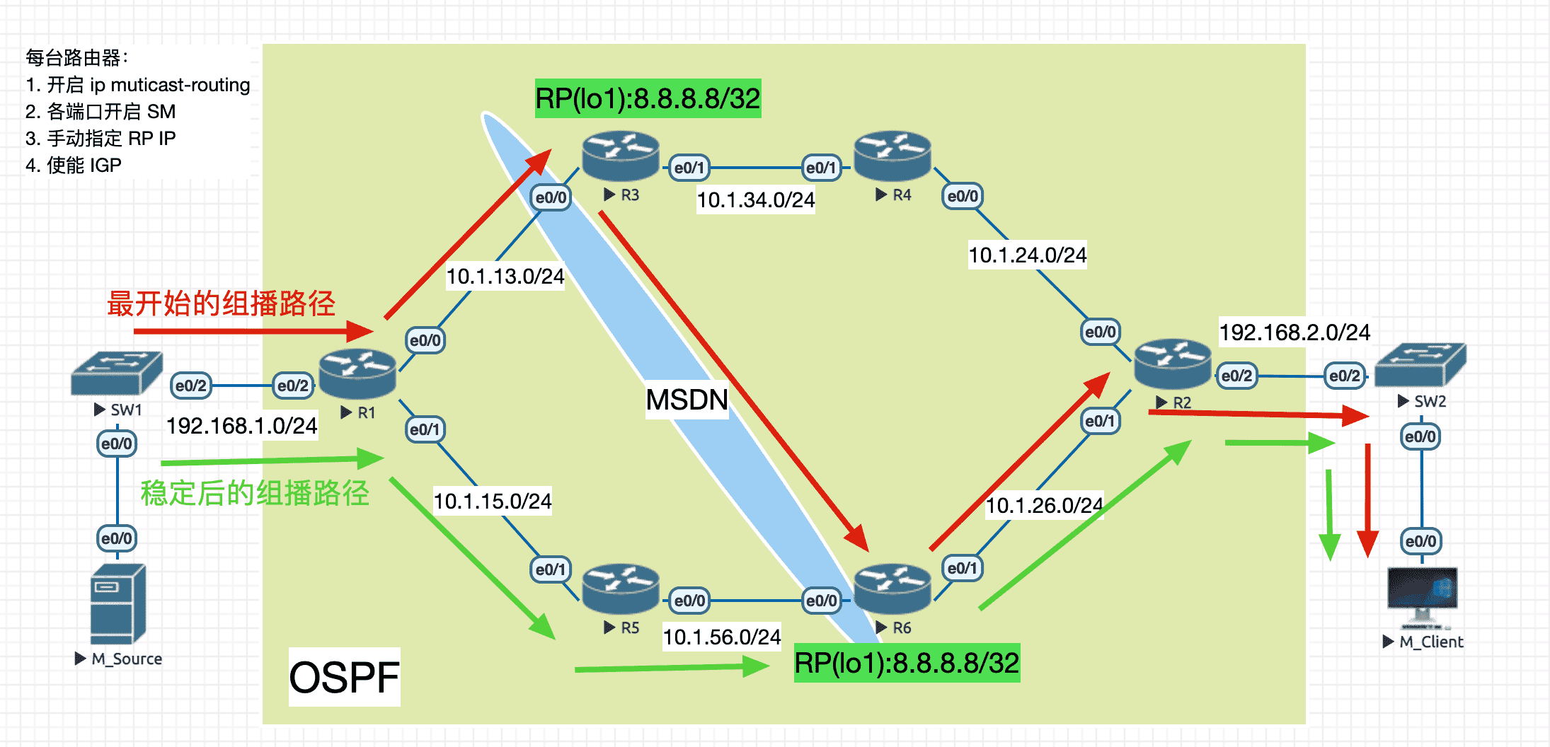
Figure 20: 拓扑
R3 (R6 配置类似)
interface Loopback1
 ip address 8.8.8.8 255.255.255.255
 ip pim sparse-mode
!
interface Ethernet0/0
 ip address 10.1.13.3 255.255.255.0
 ip pim sparse-mode
 duplex auto
!
interface Ethernet0/1
 ip address 10.1.34.3 255.255.255.0
 ip pim sparse-mode
 duplex auto
!
router ospf 1
 router-id 3.3.3.3
 network 8.8.8.8 0.0.0.0 area 0
 network 10.1.13.3 0.0.0.0 area 0
 network 10.1.34.3 0.0.0.0 area 0
ip pim rp-address 8.8.8.8 ! 虽然本身是 RP ,但这条配置必须使用
ip msdp peer 10.1.56.6 connect-source Ethernet0/0 remote-as 1
Client join 后观察 mroute
R1#sh ip mroute
IP Multicast Routing Table
..
(*, 224.0.1.40), 02:10:25/00:02:37, RP 8.8.8.8, flags: SJPL
  Incoming interface: Ethernet0/0, RPF nbr 10.1.13.3
  Outgoing interface list: Null
R3#sh ip mroute
IP Multicast Routing Table
...
(*, 224.0.1.40), 00:43:39/00:02:54, RP 8.8.8.8, flags: SJCL
  Incoming interface: Null, RPF nbr 0.0.0.0
  Outgoing interface list:
    Ethernet0/1, Forward/Sparse, 00:42:53/00:02:54
    Ethernet0/0, Forward/Sparse, 00:43:39/00:02:28
R6#sh ip mroute
IP Multicast Routing Table
...
(*, 239.1.1.1), 00:44:58/00:02:46, RP 8.8.8.8, flags: S
  Incoming interface: Null, RPF nbr 0.0.0.0
  Outgoing interface list:
    Ethernet0/1, Forward/Sparse, 00:44:58/00:02:46

(*, 224.0.1.40), 00:45:04/00:02:22, RP 8.8.8.8, flags: SJCL
  Incoming interface: Null, RPF nbr 0.0.0.0
  Outgoing interface list:
    Ethernet0/0, Forward/Sparse, 00:45:04/00:02:22
可见 R6 上的共享树信息不会通过 MSDP 传递给 R3 。
Source 发出第一个组播数据

Figure 21: R3/e0/0 上的 Source-Active 数据包 (payload 其实是 Register 消息中的 payload)
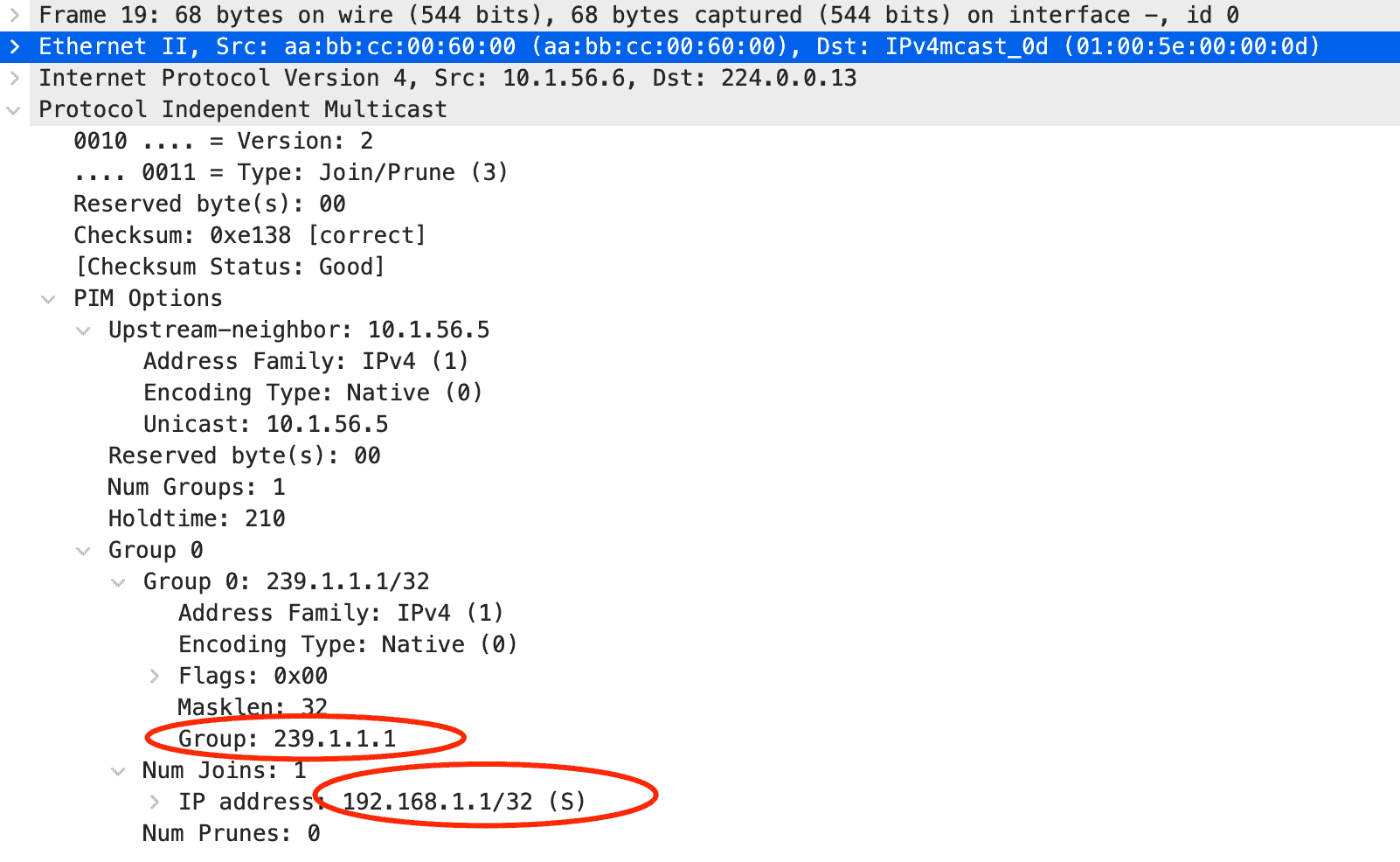
Figure 22: R6/e0/0 会发出 PIM-Join 消息用于构建最短路径树
再观察 R1 上的组播路由表:
R1#sh ip mroute
IP Multicast Routing Table

(*, 239.1.1.1), 00:00:02/stopped, RP 8.8.8.8, flags: SPF
  Incoming interface: Ethernet0/0, RPF nbr 10.1.13.3
  Outgoing interface list: Null

(192.168.1.1, 239.1.1.1), 00:00:02/00:02:57, flags: FT ! 构建出最短路径树
  Incoming interface: Ethernet0/2, RPF nbr 0.0.0.0
  Outgoing interface list:
    Ethernet0/1, Forward/Sparse, 00:00:02/00:03:27 ! 后续组播数据从该接口转发

(*, 224.0.1.40), 02:12:15/00:02:47, RP 8.8.8.8, flags: SJPL
  Incoming interface: Ethernet0/0, RPF nbr 10.1.13.3
  Outgoing interface list: Null
8 域间组播(另一种 MSDP 的应用)
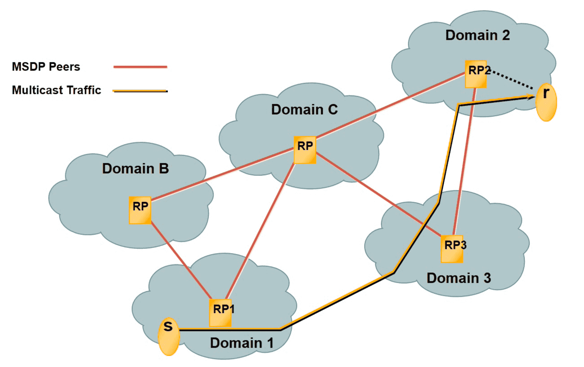
Figure 23: 应用场景
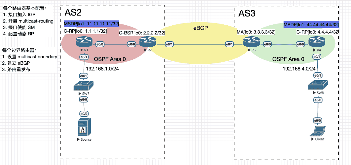
Figure 24: 实验拓扑
R1
ip multicast-routing
interface Loopback0
 ip address 1.1.1.1 255.255.255.255
 ip pim bsr-border ! 如果不配这条配置,会有如下 debug 信息(其实无伤大雅的):
 ! PIM-BSR(0): bootstrap (2.2.2.2) on non-RPF path Loopback0 (expected Ethernet0/0) or from non-RPF neighbor 1.1.1.1 (expected 10.1.12.2) discarded
 ip pim sparse-mode
!
interface Loopback1
 ip address 11.11.11.11 255.255.255.255
!
interface Ethernet0/0
 ip address 10.1.12.1 255.255.255.0
 ip pim sparse-mode
 duplex auto
!
interface Ethernet0/1
 ip address 192.168.1.254 255.255.255.0
 ip pim sparse-mode
 duplex auto
!
router ospf 2
 router-id 1.1.1.1
 network 1.1.1.1 0.0.0.0 area 0
 network 10.1.12.1 0.0.0.0 area 0
 network 11.11.11.11 0.0.0.0 area 0
 network 192.168.1.254 0.0.0.0 area 0
!
ip pim rp-candidate Loopback0
ip msdp peer 44.44.44.44 connect-source Loopback1 remote-as 3
R2
ip multicast-routing
interface Loopback0
 ip address 2.2.2.2 255.255.255.255
 ip pim sparse-mode
!
interface Ethernet0/0
 ip address 10.1.12.2 255.255.255.0
 ip pim sparse-mode
 duplex auto
!
interface Ethernet0/1
 ip address 10.1.23.2 255.255.255.0
 ip pim bsr-border ! 设置传播边界
 ip pim sparse-mode
 duplex auto
!
router ospf 2
 router-id 2.2.2.2
 redistribute bgp 2 metric 20 subnets
 network 2.2.2.2 0.0.0.0 area 0
 network 10.1.12.2 0.0.0.0 area 0
!
router bgp 2
 bgp router-id 2.2.2.2
 no bgp default ipv4-unicast ! 使用基于地址簇的写法
 neighbor 10.1.23.3 remote-as 3
 !
 address-family ipv4
  redistribute ospf 2 metric 20
  neighbor 10.1.23.3 activate
 exit-address-family
!
ip pim bsr-candidate Loopback0 0
R3
ip multicast-routing
interface Loopback0
 ip address 3.3.3.3 255.255.255.255
 ip pim sparse-mode
!
interface Ethernet0/0
 ip address 10.1.34.3 255.255.255.0
 ip pim sparse-mode
 duplex auto
!
interface Ethernet0/1
 ip address 10.1.23.3 255.255.255.0
 ip pim sparse-mode
 ip multicast boundary AUTO_RP_BOUND
 duplex auto
!
router ospf 3
 router-id 3.3.3.3
 redistribute bgp 3 metric 20 subnets
 network 3.3.3.3 0.0.0.0 area 0
 network 10.1.34.3 0.0.0.0 area 0
!
router bgp 3
 bgp router-id 3.3.3.3
 no bgp default ipv4-unicast
 neighbor 10.1.23.2 remote-as 2
 !
 address-family ipv4
  redistribute ospf 3 metric 20
  neighbor 10.1.23.2 activate
 exit-address-family
!
ip pim autorp listener
ip pim send-rp-discovery Loopback0 scope 255
!
ip access-list standard AUTO_RP_BOUND
 deny   224.0.1.39
 deny   224.0.1.40
 permit any
!
R4
ip multicast-routing
interface Loopback0
 ip address 4.4.4.4 255.255.255.255
 ip pim sparse-mode
!
interface Loopback1
 ip address 44.44.44.44 255.255.255.255
!
interface Ethernet0/0
 ip address 10.1.34.4 255.255.255.0
 ip pim sparse-mode
 duplex auto
!
interface Ethernet0/1
 ip address 192.168.4.254 255.255.255.0
 ip pim sparse-mode
 duplex auto
!
router ospf 3
 router-id 4.4.4.4
 network 4.4.4.4 0.0.0.0 area 0
 network 10.1.34.4 0.0.0.0 area 0
 network 44.44.44.44 0.0.0.0 area 0
 network 192.168.4.254 0.0.0.0 area 0
!
ip pim autorp listener
ip pim send-rp-announce Loopback0 scope 255
ip msdp peer 11.11.11.11 connect-source Loopback1 remote-as 2
在 R4 上查看通过 MSDP 收到的源信息
R4#sh ip msdp sa-cache
MSDP Source-Active Cache - 1 entries
(192.168.1.1, 239.1.1.1), RP 1.1.1.1, AS ?,00:00:00/00:05:59, Peer 11.11.11.11
9 组播应用程序
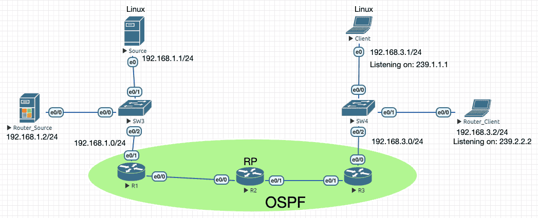
Figure 25: 实验拓扑
Linux Server 上 ping 组播地址时,TTL 默认为 1 ,可以使用 iptables -t mangle -A OUTPUT -d 239.0.0.0/8 -j TTL --ttl-set 128 进行设置先。6
Linux Client 上如果要响应组播 ICMP Request 则要设置 echo 0 > /proc/sys/net/ipv4/icmp_echo_ignore_broadcasts 。7
SW3 上要先关闭 IGMP Snooping ,不然 SW3/e0/2 不会转发组播源的数据(ICMP 不影响居然) 。
Linus Source
import socket
import struct
import sys

multicast_addr = sys.argv[1] if len(sys.argv) > 1 else '224.0.0.1'
bind_addr = '0.0.0.0'
port = 3000

sock = socket.socket(socket.AF_INET, socket.SOCK_DGRAM)
membership = socket.inet_aton(multicast_addr) + socket.inet_aton(bind_addr)

sock.setsockopt(socket.IPPROTO_IP, socket.IP_ADD_MEMBERSHIP, membership)
sock.setsockopt(socket.SOL_SOCKET, socket.SO_REUSEADDR, 1)

sock.bind((bind_addr, port))

try:
    while True:
        message_bytes, address = sock.recvfrom(255)
        message = message_bytes.decode()
        print(f'{message} <= {address}')
finally:
    sock.close()
Linux Client
import socket
import struct
import sys

multicast_addr = sys.argv[1] if len(sys.argv) > 1 else '224.0.0.1'
bind_addr = '0.0.0.0'
port = 3000

sock = socket.socket(socket.AF_INET, socket.SOCK_DGRAM)
membership = socket.inet_aton(multicast_addr) + socket.inet_aton(bind_addr)

sock.setsockopt(socket.IPPROTO_IP, socket.IP_ADD_MEMBERSHIP, membership)
sock.setsockopt(socket.SOL_SOCKET, socket.SO_REUSEADDR, 1)

sock.bind((bind_addr, port))

try:
    while True:
        message_bytes, address = sock.recvfrom(255)
        message = message_bytes.decode()
        print(f'{message} <= {address}')
finally:
    sock.close()